Article sections
Introduction
Congratulations! You are about to build a drone with the BrainFPV RADIX LI, the worlds first 20mm x 20mm flight controller with a graphical on-screen display (gOSD). Below is a step-by-step guide that walks you through the process of building your drone with the RADIX LI. For information on what tools you need etc., make sure to have a look at the RADIX Hardware Manual as well.
Step-by-Step Guide
Connect FPV Camera
Connect your camera to your RADIX LI as shown below. 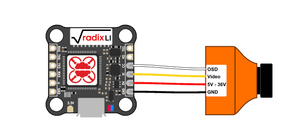
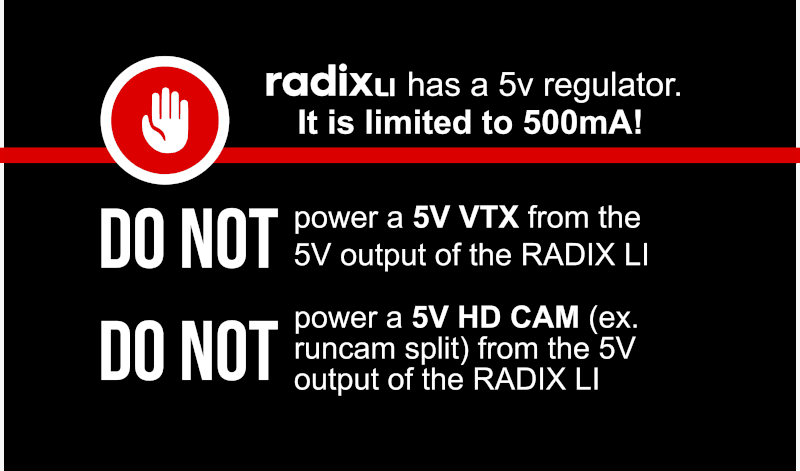
- 5V / GND: Connect those to power the camera. Keep in mind that the 5V regulator of the RADIX LI is rated for 500mA, so don’t power an HD camera like the RunCam Split Mini from the RADIX LI, as HD cameras draw more than 500mA.
- Video: This is the video output of the camera, it needs to be connected to the VI (Video Input) of the RADIX LI.
- OSD: See notes on camera control below.
Camera Control
Some FPV cameras can be controlled by the flight controller. This is useful for quickly changing camera settings in the field. Older cameras have an “OSD” input, which was originally designed to have a little joystick board that comes with the camera attached to it. Most of those cameras can be controlled by connecting the OSD input the the CC (Camera Control) pad of the RADIX LI. Due to differences between cameras, this doesn’t work reliably with all cameras and you may need to change settings. For more information, see here.
There are newer cameras on the market that can be controlled using a serial port (“UART”). If you want to use camera control with those cameras, you can connect the TX / RX pair on the camera to any unused TX / RX pair on the RADIX LI (e.g. TX6 / RX6 for UART6). Keep in mind that the wires need to be crossed, i.e., connect RX from the camera to TX on the RADIX LI and vice versa.
Connect Video Transmitter
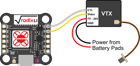
To transmit the video to your FPV goggles, you need a video transmitter (VTX). The VTX is connected to the RADIX LI as follows:
- Video: This is the video input of the VTX, it needs to be connected to the VO (Video Output) pad of the RADIX LI.
- CTL: Most modern video transmitters have a feature that allow them to be configured using a serial port, which will let you change the transmit power and frequency using the OSD menu of the RADIX FC. On the commonly used TBS Unify Pro video transmitters, the Audio input is used for this functionality. Connect this signal to the TX1 (UART1 TX) pad of the RADIX LI. Note that this connection is optional, not using it will allow you to use UART1 for a different functionality.
NOTE: UART6 (TX6) does not support SmartAudio (and other VTX protocols). Any other UART can be used. - Powering the VTX: Many video transmitters available today are “HV” video transmitters, which means they can be powered from the full battery voltage. If you have such a VTX, connect the GND (black) and power input (red) to the negative (-) and positive (+) battery pads of your 4-in-1 ESC.NOTE: The 5V regulator of the RADIX LI is not designed to power video transmitters. If you have a 5V video transmitter, you will need to use a separate 5V regulator to power it.
Connect RC Receiver
The RADIX LI can be used with a large number of different RC receivers. Pretty much any “single wire” receiver, i.e., serial or PPM (Pulse Position Modulation) is supported. Older PWM receivers that use a separate wire per channel are not supported. The connection of the RC receiver for the RADIX LI is the same as for the full size RADIX flight controller, please refer to the RADIX manual for more information.
Connect Buzzer
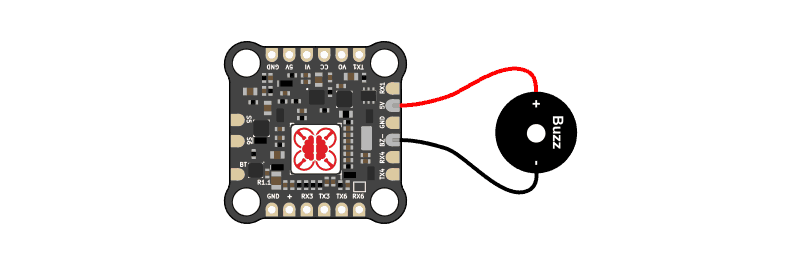
You can connect a 5V buzzer to the RADIX LI. The buzzer is useful for indicating warnings and also for locating your drone when you crash in tall grass etc. Any DC (direct current) 5V buzzer should work. The current drawn by the buzzer should be less than 200mA, which should be the case for pretty much every buzzer sold for drones out there. Note that modern ESC’s can use the motors to buzz, which is maybe not as loud as an actual buzzer, but loud enough for locating your drone. So installing a buzzer is optional, as long as you setup the motors to be used as buzzer, or if you don’t want a buzzer at all and risk losing your precious drone ;).
If you use a buzzer, wire it as follows
Connect RADIX LI to 4-in-1 ESC
The RADIX LI is designed to be compatible with any 4-in-1 ESC currently available. The RADIX LI comes with a cable kit containing a pre-wired harness and 10 pin, 8 pin, 7 pin connectors. The kit allows you to make a cable that is compatible with your ESC. The following signals always need to be connected:
- Motor outputs: S1, S2, S3, S4
- Ground (GND)
- Battery voltage (VBAT, up to 6S max!)
In addition, the RADIX LI has pins for current sensing, ESC telemetry (RX4), and RGB LEDs. Some 4-in-1 ESCs have an current sensor with an analog current sensor output, this output needs to be connected to the current sensor input of the RADIX LI. It will allow you to monitor how much current you are drawing from the battery and display this information in the onscreen display.
Newer ESCs (typically using BLHeli_32) sometimes also have a telemetry output, which can be connected to the RX4 (UART4 RX) pin of the RADIX LI. This allows the ESC to send additional information like ESC temperature, RPM, and current draw per motor to the flight controller. In practice, ESC telemetry has limited use and doesn’t improve the flight performance. So you may choose not to make this connection and use UART4 for some other function (for example for connecting a GPS).
Below are instructions for particular 4-in-1 ESC’s and how to connect them to the RADIX LI.
Hobbywing XRotor Micro 4-in-1 40A ESC
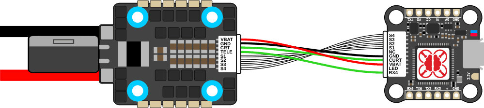
The Hobbywing XRotor Micro 4-in-1 40A ESC is one of the best ESC’s on the market to be used with the RADIX LI flight controller. It supports up to 6S and runs BLHeli_32, so you get all the latest features (bi-directional DSHOT for RPM filtering, etc.). To connect it to the RADIX LI, use the cable kit included with the RADIX LI to make a custom cable. On the ESC side, use the empty 8-pin connector housing and insert the cables as shown below.
Note: The green wire going from TELE to RX4 is optional. It is used for ESC telemetry, which only isn’t very useful. The ESC has an analog current sensor, so you will get current sensing without telemetry. If you don’t connect the telemetry wire, you can use UART4 of the RADIX LI for a different peripheral, e.g., a GPS.
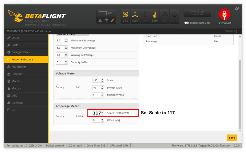
The current sensor of this 4-in-1 ESC has a calibration value of 11.75 mV/A, so set the current scale in betaflight to 117:
Spedix IS25 4-in-1 ESC
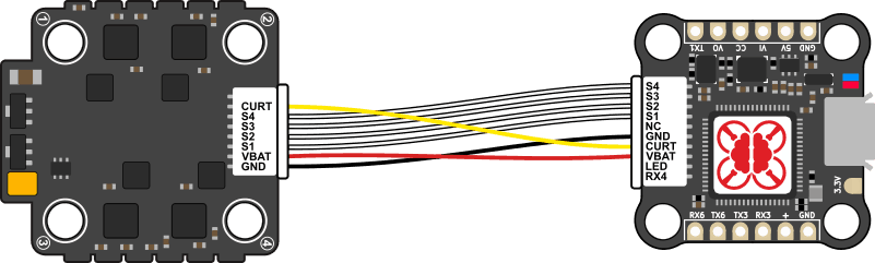
The Spedix IS25 4-in-1 ESC is a very nice BLHeli_S based ESC with an analog current sensor. The ESC needs to be connected to the RADIX LI as shown below. The IS25 ESCs sold by us include a wire that makes them plug-and-play with the RADIX LI. Nevertheless, it is a good idea to always double check the pinout and make sure the cable in pinned correctly.
Install the RADIX LI and 4-in-1 ESC on your Quadcopter Frame
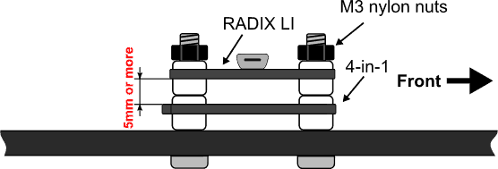
The RADIX LI is designed to be mounted on your quadcopter using M3 bolts. Either metal or nylon bolts can be used. The 4-in-1 ESC is mounted underneath the RADIX LI on the frame. Use silicone grommets or nylon nuts to obtain spacing between the frame and the 4-in-1 and the 4-in-1 ESC and the RADIX LI. This is illustrated below. Make sure the spacing between the ESC and the RADIX LI is at least 5 mm. If it is closer, the switching noise from the ESC can cause video interference and possibly other problems.
Wiring
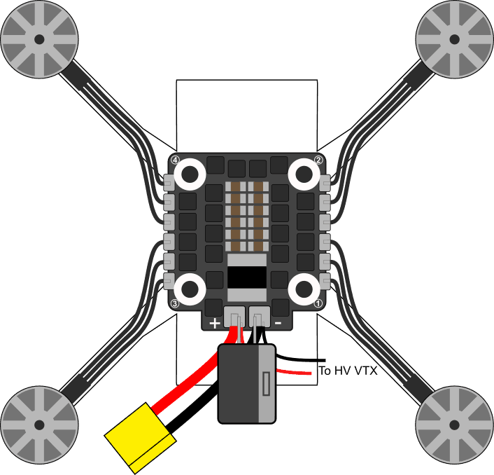
Wire the 4-in-1 ESC as shown below. Each motor is attached to the battery pads in the corresponding corner. Don’t worry about in which order the wires of each motor attached to the 4-in-1 ESC; swapping two wires of a motor will reverse the motor direction, but this can later be changed in software when configuring your ESC’s. Attach the battery cables to the large solder pads on the back of the 4-in-1 ESC. Also solder one of the capacitors included with the ESC to the battery pads. Make sure you install the capacitor the correct way; the gray band on it indicates the negative terminal. When finished, it should look like this:
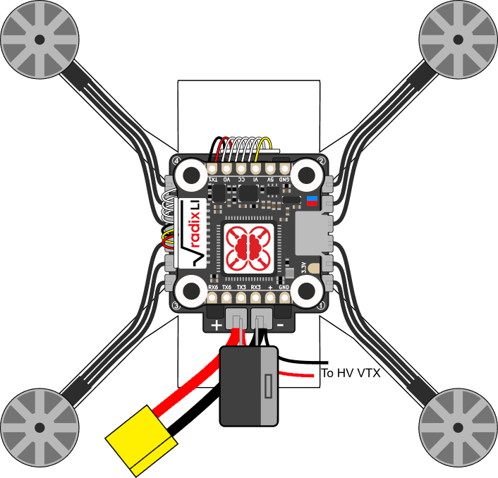
Stack RADIX LI on Top of 4-in-1 ESC
Finally, stack the RADIX LI on top of the 4-in-1 ESC and use the cable (see above) to connect them.
RADIX LI Quick Reference
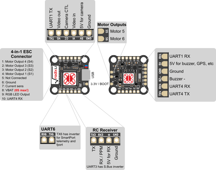
Remember, the 5V regulator of the RADIX LI is rated for 500mA, so do not use it to power a 5V video transmitter or an HD camera