Article sections
Introduction
Things You Will Need to Build Your Drone
To build your FPV drone using the RADIX FC / PB or 4-in-1 ESC, you need a several different components. For a typical quadcopter drone you will need:
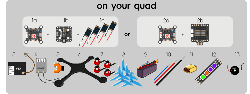
- The RADIX FC + the RADIX PB + 4 ESCs (either BLHeli_32, BLHeli_S, or KISS)
- The RADIX FC + the 4-in-1 ESC
- An FPV video transmitter and antenna. The TBS Unify Pro HV is a good choice
- A RC receiver that works with your RC transmitter
- A FPV camera
- A quadcopter frame
- 4 motors
- Plenty of propellers, as you will likely break many in crashes 😉
- LiPo battery packs
- Wires:
- 14 AWG or 16 AWG 16 wire to connect the LiPo battery
- 16 AWG or 18 AWG to connect the ESC’s
- 28 AWG or 30 AWG to connect other low power components (RC receiver etc.)
*For best results, use flexible silicone wire.
- XT60 male (or other) power connector, so you can connect the LiPo battery to your drone
- Optional: Programmable RGB LED’s (WS2812B compatible) if you want shiny lights on your drone
- Optional: A 5V buzzer. Note: modern ESC’s can use the motors as buzzer, so this isn’t really needed
Not sure what components to get? Check out the Brain Configurator that allows you to configure and order a quadcopter with all BrainFPV recommended components 🙂
In addition, you need the following on the ground when flying:
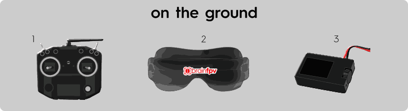
- A RC trasnmitter
- FPV video goggles or a screen with a video receiver
- A charger to charge your LiPo battery packs
To build your drone, you will need:
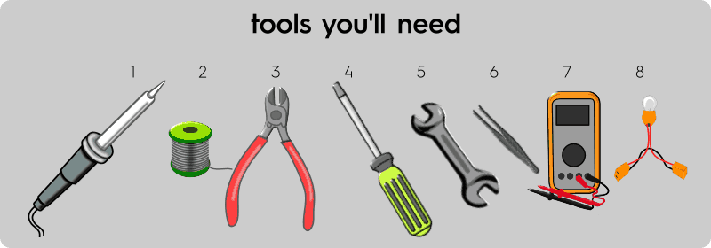
- A soldering iron. Get a decent iron with at least 40W power and exchangeable tips. Check out this video for basic soldering instructions
- Solder. We recommend Kester 60/40 rosin core solder.
***Note: This solder contains lead, which is toxic! Make sure to wash your hands after handling solder!- Optional, but recommended: Solder wick to remove excess solder
- Cable cutters
- Screw drivers
- Wrenches (depending on the quadcopter frame you use)
- Tweezers; they are handy for holding cables when soldering
- Optional: A multimeter to measure voltage and check continuity
- Optional: A “smoke stopper“, which is a device that limits the current and can prevent damage if you miswired something
Should I Be using the RADIX PB or 4-in-1 ESC?
The RADIX FC can be used with either the RADIX PB and separate ESC’s OR the 4-in-1 ESC. Which is better to use depends on your goals and personal preference. Some of the pros/cons are:
Advantages of using the RADIX PB with separate ESC’s:
- You can replace individual ESC’s if they get damaged
- You have more ESC options and can use ESC’s with telemetry
- You can use up to 8S batteries
- You can use higher power ESC’s/motors, as the ESC’s are mounted on the arms of the quadcopter and get better cooling from airflow
- You can draw more current on 5V, so you can e.g. use more LED’s or a 5V video transmitter
Advantages of using the 4-in-1 ESC:
- Shorter build time with less soldering
- Overall lighter than when using RADIX PB with separate ESC’s
- Allows you to use frames with skinnier arms, which have less air drag and are potentially faster
General Tips and Tricks
Here are some tips, tricks and best practices we recommend when building and flying drones:
- Use consistent wire colors. Most commonly used are:
- RED for positive power (e.g. 5V, battery voltage)
- BLACK for ground (GND)
- YELLOW for video signals
- WHITE, GREEN, and BLUE for other signals (serial, motor signals, etc).
- Practice soldering on some old or defective components. Check out this video for basic soldering instructions
- Always remove the propellers when working on your drone! The propellers are sharp and they can seriously injure you if the motors accidentally spool up with propellers attached.
- Be careful when handling your drone with the battery and propellers attached. Always assume the propellers could spin up at any moment.
- Always follow applicable laws when flying. In the United States, follow the guidelines published by the Federal Aviation Administration: https://www.faa.gov/uas
- Some video and radio equipment may require a amateur (HAM) license to be operated legally.
Step-by-Step Guide
Below you find step-by-step instructions on how to build your FPV drone using the RADIX FC and the RADIX PB or the 4-in-1 ESC. Note that you may want to scroll down and first follow the instructions on how to wire up the RADIX PB or 4-in-1 ESC and then follow the instructions below on how to connect the FPV camera, RC receiver, etc. to your RADIX FC.
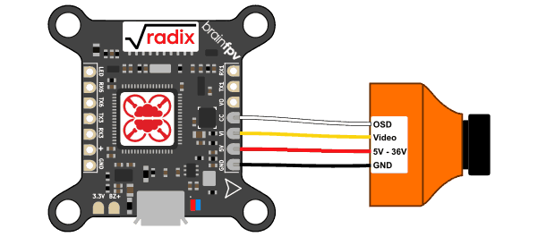
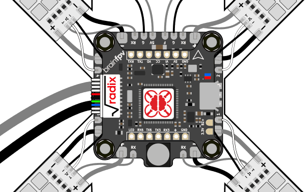
Connect FPV Camera
Connect your FPV camera to the RADIX FC as shown below. These days, most FPV cameras work reliably when powered with 5V, so the best way is to directly connect it to the 5V output on the RADIX FC. If your camera needs a higher voltage and can handle the full battery voltage (e.g. 4S LiPo etc), you can alternatively power it from the F output on the RADIX PB, which provides filtered battery voltage. The camera has a video and optional “OSD” connection:
- Video: This is the video output of the camera, it needs to be connected to the VI (Video Input) of the RADIX FC
- OSD: Many cameras have a “OSD” input that can be used to access the internal OSD of the camera to change camera settings. You can connect this signal to the CC (Camera Control) output of the RADIX FC, which will let you access the camera OSD menu and change camera settings using your RC transmitter sticks. Note that this functionality is separate from the OSD of the RADIX FC. Also, this connection is optional and the cable does not need to be connected if you don’t want this functionality.
Connect Video Transmitter
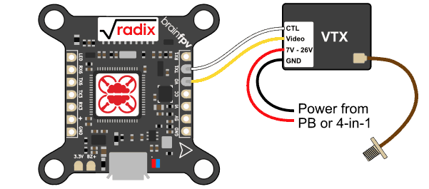
To transmit the video to your FPV goggles, you need a video transmitter (VTX). The VTX is connected to the RADIX FC as follows:
- Video: This is the video input of the VTX, it needs to be connected to the VO (Video Output) pad of the RADIX FC.
- CTL: Most modern video transmitters have a feature that allow them to be configured using a serial port, which will let you change the transmit power and frequency using the OSD menu of the RADIX FC. On the commonly used TBS Unify Pro video transmitters, the Audio input is used for this functionality. Connect this signal to the TX1 (UART1 TX) pad of the RADIX FC. Note that this connection is optional, not using it will allow you to use UART1 for a different functionality.
NOTE: UART6 (TX6) does not support SmartAudio (and other VTX protocols). Any other UART can be used. - Powering the VTX: Many video transmitters available today are “HV” video transmitters, which means they can be powered from the full battery voltage. If you have such a VTX and are using the RADIX PB, connect the GND (black) and power input (red) to the G (ground) and F (Filtered battery voltage) output of the RADIX PB, respectively. Note: The RADIX PB is rated up to 8S voltage (35V) and most video transmitters available today can’t handle such high voltages. So if you use 8S, you should use a 5V VTX, otherwise you will damage your VTX! If you use a 5V video transmitter, connect it to GND and 5V on the RADIX PB. We don’t recommend powering the VTX by connecting it to 5V / GND of the RADIX FC, as the VTX draws a lot of current, which could cause potential problems. If you are using the 4-in-1 ESC, you should use a HV video transmitter and directly connect it to the battery pads of the ESC. Make sure to install the capacitor to reduce motor noise!
Connect RC Receiver
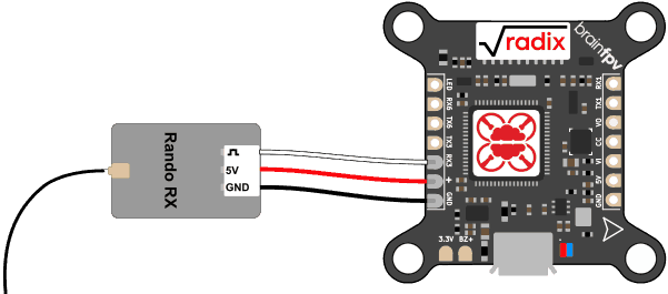
The RADIX FC can be used with a large number of different RC receivers. Pretty much any “single wire” receiver, i.e., serial or PPM (Pulse Position Modulation) is supported. Older PWM receivers that use a separate wire per channel are not supported. Below you find instructions on how to connect the most commonly used receivers.
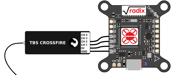
TBS Crossfire Receiver
The Team BlackSheep (TBS) Crossfire system is a popular long-range system that operates on the 915MHz / 868MHz frequency band. When using a Crossfire receiver with the RADIX FC, connect it as shown in the diagram below.
- CH 1: Connect this wire to RX3 (UART3 RX). Make sure to set this output to CRSF TX when configuring the Crossfire system.
- CH 2: Connect this wire to TX3 (UART3 TX). Make sure to set this output to CRSF RX when configuring the Crossfire system.
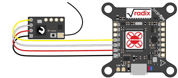
Crossfire Nano Rx
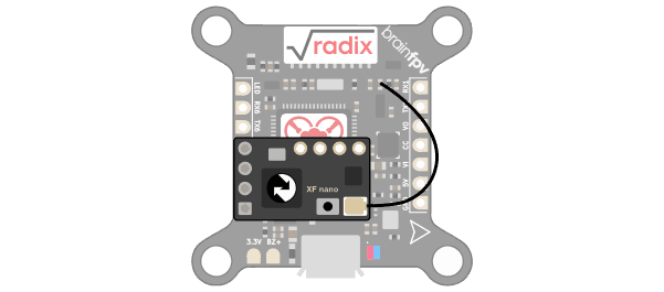
The Crossfire Nano Rx can be wired or directly stacked onto the RADIX FC. If you stack it, use a pin header to connect the two and use some double sided tape to prevent the receiver from bouncing around. Also, keep in mind that it will be difficult to de-solder the receiver from the RADIX FC if you stack them. The Crossfire Diversity Nano Rx can be wired / stacked the same way.
Note: If you use the backup battery functionality of the Diversity Nano Rx, DO NOT power the Rx from the “+” pad next to RX3. It draws too much current and will damage the RADIX. Instead, power it from a different 5V pad. If you don’t use the battery backup function, powering it from the “+” pad is fine.
Wired:
Stacked:
Crossfire Micro Rx
Wire the Micro Rx as shown below. Be careful when doing so; for unknown and mysterious reasons, TBS decided to make all the wires black, so be careful not to confuse them.
FrSky S.Bus / S.Port Receiver
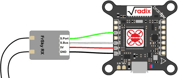
The diagram below shows how to connect a FrSky receiver to the RADIX FC. Note that the receiver in the diagram is generic, as there are several different receivers made by FrSky, so the exact pinout and coloring of wires may be different for the receiver you use. In addition to ground (GND, black) and 5V (red), most modern FrSky receivers have two signals that need to be connected to the flight controller:
- S.Bus: This serial signal carries the RC information from the receiver to the flight controller. On RADIX FC, it needs to be connected to RX3 (UART3, RX) as this input features a signal inverter that is needed for S.Bus.
- S.Port: The S.Port (SmartPort) telemetry signal carries information back and forth between the RADIX FC and your RC transmitter. It allows you to e.g. see the battery voltage on your transmitter, change settings using scripts etc. Note: This connection is optional, i.e., if you don’t want telemetry you don’t need to connect this signal. This will allow you to use UART6 for a different peripheral. On RADIX FC, this signal needs to be connected to TX6 (UART6, TX), as this input has a bi-directional inverter that is needed for S.Port.
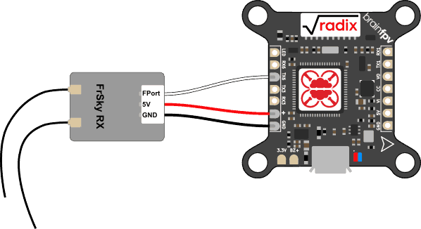
FrSky FPort Receiver
FPort is a newer receiver protocol by FrSky. Unlike older receivers, which used S.Bus for RC commands and S.Port for telemetry (and therefore used two serial ports / UARTs on your flight controller), FPort only needs a single wire and UART for both RC commands and telemetry. Like other FrSky protocols, it is an inverted protocol and needs to be connected to TX6 of the RADIX FC, which features the bi-directional inverter needed. If you use a receiver that has been modified to use un-inverted data, connect it to TX3. Please make sure to follow the instructions on how to configure your receiver when setting up Betaflight.
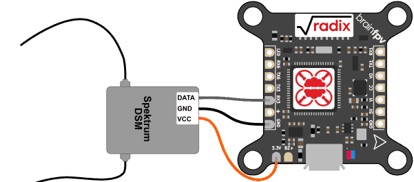
Spektrum DSM Receiver
If you use a Spektrum DSM or DSMX satellite receiver, connect it as shown below. Unlike pretty much every other receiver on the planet, the satellite receivers need to be powered using 3.3V instead of 5V, so make sure to connect the orange wire to the 3.3V pad on the RADIX FC.
- Gray wire (DATA): Connect this wire to RX3 (UART3 RX) on RADIX FC.
- Orange wire (VCC): This wire needs to be connected the the 3.3V pad on RADIX FC. Don’t connect it to 5V (+), or you will damage your receiver!
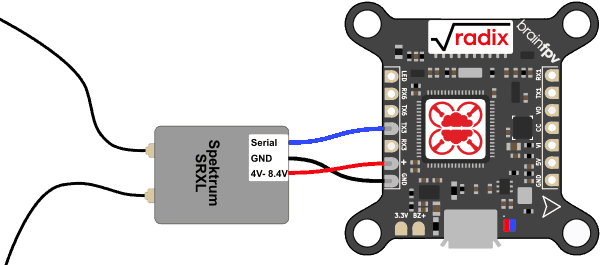
Spektrum SRXL Receiver
Some newer Spektrum receivers, e.g., the SPM4649T, support the SRXL protocol and they can be used with 5V (amazing!). Wire the receiver as shown below.
- Serial: Connect this signal to the TX3 (UART3 TX) pad on the RADIX FC. As SRXL is a bi-directional protocol, i.e., RC data and telemetry data is transmitted over a single wire, we connect it to TX3 instead of RX3. Make sure to follow the extra steps to enable telemetry when setting up the receiver in Betaflight, otherwise it won’t work.
Other Receivers
Apart from the receiver types listed above, the RADIX FC can be used with other serial or PPM (Pulse Position Modulation) receivers, as long as they are supported in Betaflight. Pretty much all receivers can be powered from 5V. If in doubt, consult the manual of your receiver. The signal wire needs to be connected to the RX3 on RADIX FC, which can function as UART3 RX for serial receivers, or PPM input for PPM receivers.
Connect Buzzer
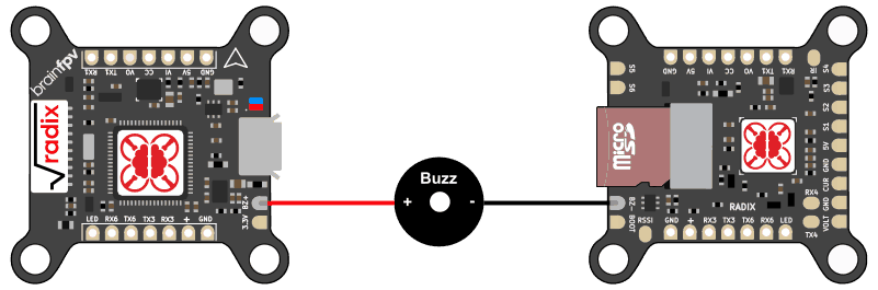
You can connect a 5V buzzer to the RADIX FC. The buzzer is useful for indicating warnings and also for locating your drone when you crash in tall grass etc. Any DC (direct current) 5V buzzer should work with the RADIX FC. The current drawn by the buzzer should be less than 200mA, which should be the case for pretty much every buzzer sold for drones out there. Note that modern ESC’s can use the motors to buzz, which is maybe not as loud as an actual buzzer, but loud enough for locating your drone. So installing a buzzer is optional, as long as you setup the motors to be used as buzzer, or if you don’t want a buzzer at all and risk losing your precious drone ;).
If you use a buzzer, wire it as follows. The buzzer BZ+ pad is on top of the RADIX FC and the BZ- pad is on the bottom:
Connect GPS
You can connect a Global Positioning System (GPS) receiver to the RADIX FC. Having a GPS on board allows you to see the coordinates of your location in the OSD (very useful for finding your drone after a crash) and you can display the ground speed as well. In addition, you can use “GPS Rescue Mode” with Betaflight or Return-to-Home (RTH) with iNAV for autonomously flying the drone back to you if for example the video malfunctions or if you lose connection between your RC transmitter and receiver. Note that this functionality is considered somewhat experimental and you should only rely on it after you have tested it several times and you are sure it works reliably.
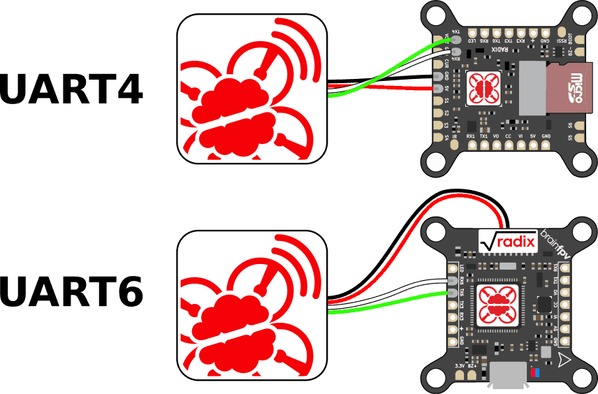
We recommend using the BrainFPV GPS, but any module with a uBlox Neo-M8 chipset will work. The GPS will need to be connected to GND / 5V of either the RADIX FC or the RADIX PB. The serial wires of the GPS (TX and RX) need to be connected to a RX / TX pair of the RADIX FC. Note that the wires are crossed, i.e., TX of the GPS connects to RX of the RADIX FC and vice versa.
If you connect the GPS to UART4, connect the wires to the RX4 / TX4 pair on the bottom of the RADIX FC, as shown below. Note that if you already use UART4 for ESC telemetry (RX4 is on the 4-in-1 ESC connector), you will need to use a different UART that is currently unused. For example, UART6. Both options are shown below
Note that many GPS units include a magnetometer (compass) that needs to be connected to the flight controller using I2C (SDA and SCL wires). This isn’t supported by the RADIX FC, so you can leave those wires unconnected. For “GPS Rescue Mode” with Betaflight and fixed-wing navigation with iNAV, a compass isn’t needed. If you want to use iNAV for a multirotor with return-to-home and navigation, you will need to use a “DJI GPS” that sends the GPS and compass information over the same serial (UART) connection.
RADIX PB
Install RADIX PB on your Frame
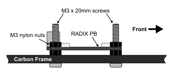
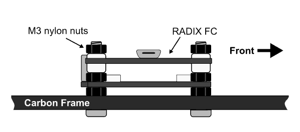
Before you wire up your RADIX PB, install it on your quadcopter frame. For a typical frame with a 3mm or 4mm thick baseplate you will need the following parts:
- M3 x 20mm screws (4x)
- M3 nylon nuts (8x) + 4x to secure RADIX FC
If your frame is thicker, you may need longer screws. The screws should be at least “frame thickness” + 15mm long. Put the screws through the frame and secure them using 4 nylon nuts. Then install the RADIX PB and secure it using 4 more nylon nuts. Make sure the capacitor (tall component) of the RADIX PB is towards the rear of your drone. The side view should look as follows:
Wiring
After mounting the RADIX PB, the motors, and the ESC’s to your frame, the next task is wiring up the RADIX PB. When soldering the thick wires to the PB, the following technique works best:
- Use your soldering iron to pre-tin the end of the wire, i.e., heat it up until the solder flows onto the wire.
- Pre-tin the pad on the PB by heating it up and let solder flow onto it.
- Attach the wire: Hold the wire using tweezers and solder it to the pad. Put your soldering iron on top of the wire and heat it until the solder on the pad and wire are both melted. Then remove the heat and hold the wire steady until the solder is solid.
If you have problems getting the solder to melt, your soldering iron may not have enough power. Try using a wider tip, increase the temperature, or if that doesn’t help, get an iron with more power.
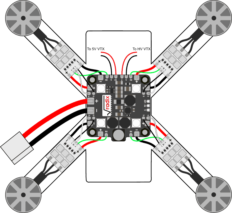
The wiring is shown below and consists of the following:
- Battery (LiPo) Connection: The LiPo is attached on the left side of the PB. Use either 16 AWG wires, or for high powered builds, 14 AWG wire. As always, use red for positive and black for negative.
- ESC Power Connections: Use either 18 AWG or 16 AWG wires to connect the ESC’s to the PB. Also use red/black wires for these connections.
- ESC Signal Connections: Connect one ESC signal output (numbered 1, 2, 3, 4) of the PB to each ESC. Use e.g. white wires for these connections.
- ESC Signal Ground Connections: On the PB, there is a ground pad (G) next to each ESC signal. Use thin black wire to connect those pads to the small ground pads on the ESC’s. This connection may seem redundant, as the ground of the ESC is already connected, but in practice the connection helps reducing noise. For best results, twist the ground wires and the ESC signal wires together.
- ESC Telemetry Connections: Some modern ESC’s (e.g. BlHeli_32 and KISS) support ESC telemetry, which allows the ESC to send data, such as current consumption and RPM, back to the flight controller. If you want to use this feature, connect the telemetry pads of the ESC’s to the RX pads of the PB. In the diagram below, green wires are used for these connections. Keep in mind that using ESC telemetry means you won’t be able to use UART4 of the RADIX FC for a different peripheral. So if you want to use UART4 for something else, or want to reduce the amount of soldering, you can choose not to wire the ESC’s for telemetry.
- Power to VTX: Connect the power and ground of your video transmitter to the pads in the front of the RADIX PB. If you use a 5V VTX, use the 5V/GND pads on the left side and if you use a HV VTX that can handle the full voltage of the LiPo battery you use, connect them to the F/GND pads on the right side.
Programmable RGB LEDs
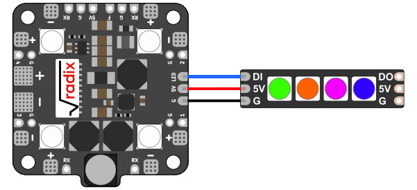
The RADIX FC can control programmable RGB LED’s, which are bright LED’s that can be used to differentiate pilots by color in a race, blink in different colors, etc. In short, they make your drone look cool and help other pilots to better see you, especially at night or indoors. This is why the RADIX PB includes four programmable RGB LED’s, so you get some bling without any additional wiring! However, you can add even more LED’s using the LED output of the RADIX PB.
The LED’s are wired as shown below. Any LED strip with WS2812B compatible RGB LED’s will work. The LED strip will have a data input (DI) which is connected to the LED output of the RADIX PB. Naturally, you also need to connect ground (GND) and 5V. Note that the LED strip will also have a data output (DO), which allows you to daisy-chain LED strip together, i.e., you can connect the DI of a second LED strip to the DO of the first strip, and so on.
When attaching more LED’s, keep in mind that each LED consumes up to 50mA (0.05A) and the total 5V current output of the RADIX PB is limited to 2A. The flight controller, RC receiver, camera, etc also draw current. To figure out how many LED’s you can use, sum up the current drawn by each component. For example:
RADIX FC: 150mA
RC Receiver: 100mA
FPV Camera: 150mA
TOTAL: 400mA
So you have about 1.6A (2A – 400mA) left for LED’s, which is enough for a total of 32 LED’s (including the 4 LED’s on the RADIX PB). If you e.g. used a 5V video transmitter, you would only be able to use 16 LED’s, as the video transmitter alone may consume 800mA at high power levels and you would only have 800mA left for LED’s. In general, we recommend not fully maxing out the 2A current budget and keep a 200mA or so safety margin (i.e., draw only 1.8A). If you draw a lot of current, make sure the RADIX PB receives sufficient cooling from airflow.
Stack RADIX FC on Top of PB
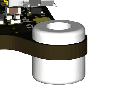
Before stacking the RADIX FC onto the RADIX PB, install the silicone anti-vibration grommets that are included with the RADIX FC. The easiest way to install them is to squeeze the grommet, put a corner through the hole of the RADIX FC, and then pull the rest of the grommet through the hole using tweezers. Don’t pull too hard, or you may damage the grommet! The short side of the grommet should be on top and it should look as follows:
After installing the grommets, stack the RADIX FC onto the RADIX PB and secure it using 4 nylon nuts. Don’t fasten the nuts too tightly, or they will squeeze the grommets and reduce their vibration isolation performance! The side view should look as follows:
To complete the installation, connect the RADIX PB to the RADIX FC using the cable that is included with the RADIX PB (10-pin to 10-pin connector):
4-in-1 ESC
The RADIX FC can be used with pretty much any 4-in-1 ESC, as long as it provides 5V to the flight controller to power it. Below you find detailed instructions for the Hobbywing X-Rotor 60A 4-in-1 ESC ( up to 6S, BLHeli_32) released in spring 2019, the Hobbywing X-Rotor 45A 4-in-1 ESC ( up to 6S, BLHeli_32) released in summer 2018 and the Hobbywing X-Rotor 40A 4-in-1 ESC (up to 5S, BLHeli_S) released in 2017.
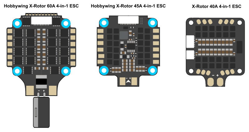
Hobbywing X-Rotor 60A 4-in-1 ESC and Hobbywing X-Rotor 45A 4-in-1 ESC
The Hobbywing 60A 4-in-1 ESC and the Hobbywing 45A 4-in-1 ESC are quite similar, which is why we combined the installation instructions for them. The main differences are that the 60A version can handle higher current, it comes with the capacitor installed, and it no longer has a 10V output.
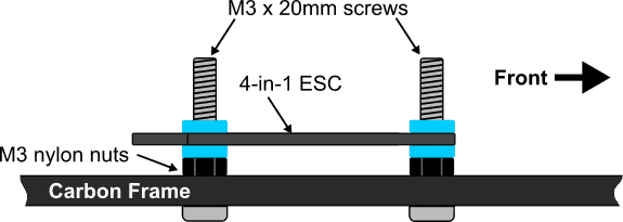
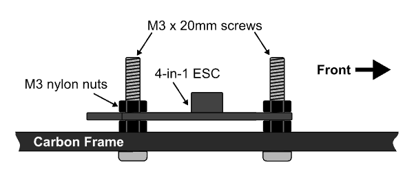
Install 4-in-1 ESC on your Frame
To install the 4-in-1 ESC on your frame, you will need the following:
- M3 x 20mm screws (at least 15mm + “frame thickness” long)
- M3 nylon nuts (4x) + 4x to secure RADIX FC
Put the screws through the frame and secure them using 4 nylon nuts. Then install the 4-in-1 ESC and secure it using 4 more nylon nuts. Make sure the battery pads (the 2 large solder pads) are facing towards the rear of your drone. The side view should look as follows:
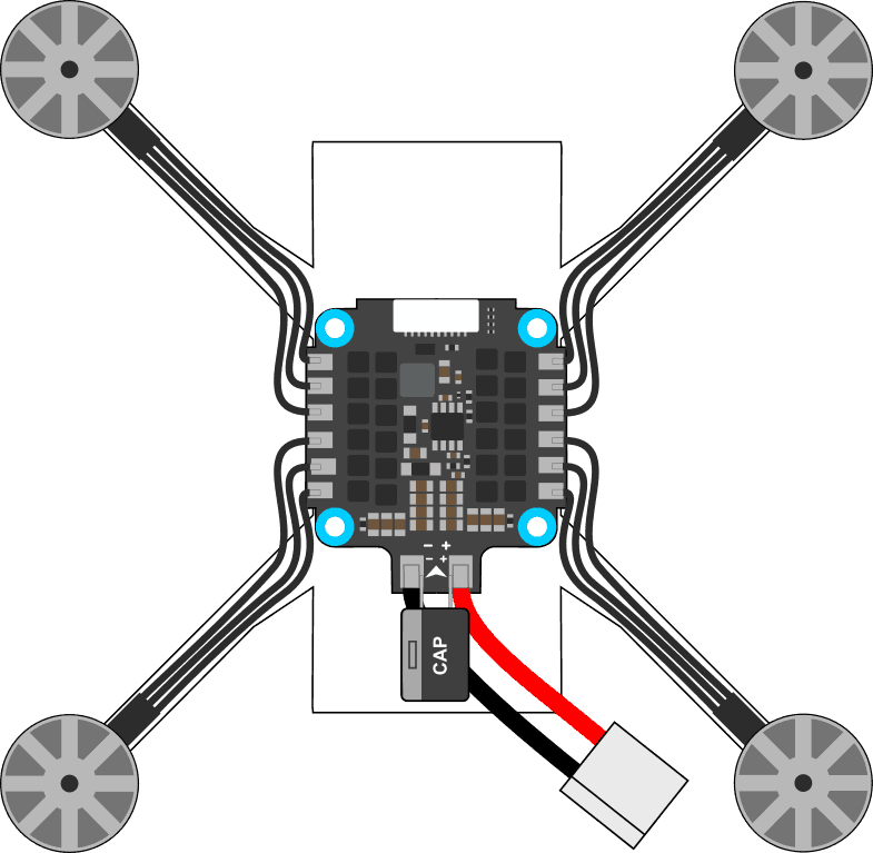
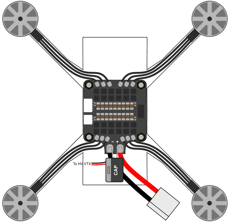
Wiring
Wire the 4-in-1 ESC as shown below. Each motor is attached to the battery pads in the corresponding corner. Don’t worry about in which order the wires of each motor attached to the 4-in-1 ESC; swapping two wires of a motor will reverse the motor direction, but this can later be changed in software when configuring your ESC’s. Attach the battery cables to the large solder pads on the back of the 4-in-1 ESC. Also solder one of the capacitors included with the ESC to the battery pads. If possible, use the larger 1000uF, 35V capacitor. If you can’t fit that in your frame, use the smaller 560uF, 35V capacitor. Make sure you install the capacitor the correct way; the gray band on it indicates the negative terminal. When finished, it should look like this:
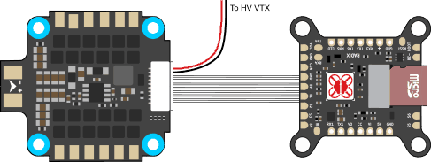
Stack RADIX FC on Top of 4-in-1 ESC
The RADIX FC stacks on top of the 4-in-1 ESC and can be connected to it using the long cable included with the 4-in-1 ESC. Before connecting them, make sure to remove the red 10V wire and the black GND wire on the flight controller side. Leaving them connected will damage the RADIX FC! You can use the 10V/GND wire from the ESC to power a HV video transmitter or a camera. Note: The 60A version of the 4-in-1 ESC no longer has the 10V output. You still need to disconnect the red and black wires on the flight controller side, but you can no longer use them to power your video transmitter. Instead, power the video transmitter directly from the battery pads.
The connection should look as follows (note that the RADIX FC is upside-down in this picture):
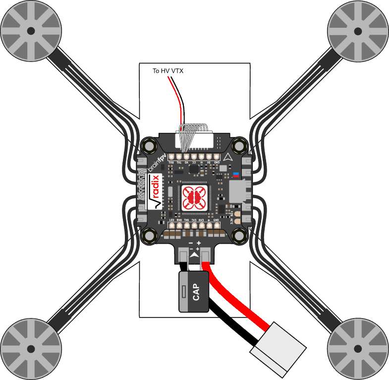
After connecting the wire, stack the RADIX FC on top of the 4-in-1 ESC with the wire “sandwiched” in between the two. From the top it should look as follows:
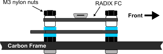
Note that when stacking the RADIX FC on top of the 4-in-1 ESC, the silicone grommets included with the RADIX need to be installed with the long side facing downwards. No additional spacing is necessary. As illustrated in the following side view:
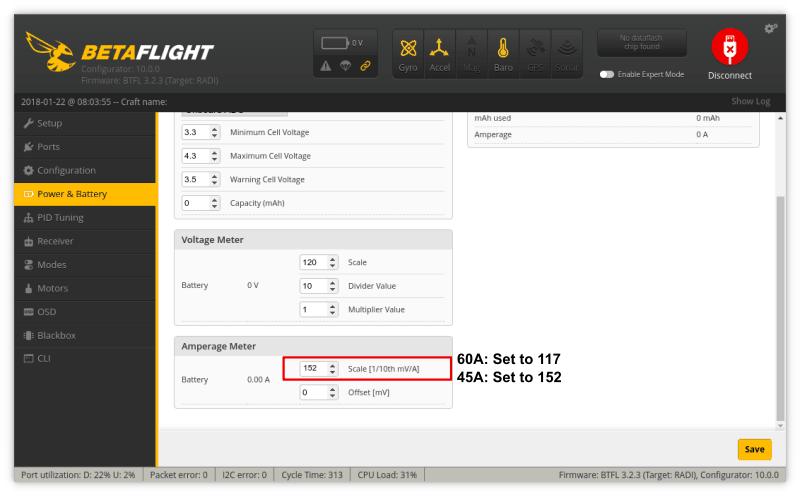
Finally, remember that the 4-in-1 ESC uses a different current sensor than the RADIX PB, so the default scale of “200” will give erroneous current measurements. When using the Hobbywing X-Rotor 60A 4-in-1 ESC, make sure to set the amperage meter scale to 117 in the Betaflight configurator. For the Hobbywing X-Rotor 45A 4-in-1 ESC, set the scale to 152.
Hobbywing X-Rotor 40A 4-in-1 ESC (up to 5S, BLHeli_S)
Install 4-in-1 ESC on your Frame
To install the 4-in-1 ESC on your frame, you will need M3 screws and nylon nuts. As described below, there are two ways of stacking the RADIX FC on top of the ESC, either with minimal stacking height (5.5mm between boards), or regular stacking height (6.5mm between boards). What hardware you need depends on the stacking height:
Minimal stacking height mounting:
- M3 x 20mm screws (at least 15mm + “frame thickness” long)
- M3 nylon nuts (8x) + 4x to secure RADIX FC
Regular stacking height mounting:
- M3 x 20mm screws (at least 17mm + “frame thickness” long)
- M3 nylon nuts (12x) + 4x to secure RADIX FC
Put the screws through the frame and secure them using 4 nylon nuts. Then install the 4-in-1 ESC and secure it using 4 more nylon nuts. Make sure the battery pads (the 2 large solder pads) are facing towards the rear of your drone. The side view should look as follows:
Wiring
Wire the 4-in-1 ESC as shown below. Each motor is attached to the battery pads in the corresponding corner. Don’t worry about in which order the wires of each motor attached to the 4-in-1 ESC; swapping two wires of a motor will reverse the motor direction, but this can later be changed in software when configuring your ESC’s. Attach the battery cables to the large solder pads on the back of the 4-in-1 ESC. At the same time, solder the 470uF 25V capacitor that is included with the ESC and the wires to the HV video transmitter to the pads. Make sure you install the capacitor the correct way; the gray band on it indicates the negative terminal. When finished, it should look like this:
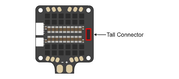
Stack RADIX FC on Top of 4-in-1 ESC
The Hobbywing 4-in-1 ESC has a tall stacking connector on the right side of the ESC, which is used by the Hobbywing flight controller, but not by the RADIX FC. When stacking the RADIX FC on top of the 4-in-1 ESC with minimum stacking height, the connector is at the location of the micro-SD card. So you have two options of stacking the RADIX FC on top of the 4-in-1 ESC:
1 : Installation with minimal stacking height (5.5mm between boards):
Install the silicone grommets and RADIX FC as described above for the RADIX PB, i.e., use one nylon nut on top of the 4-in-1 ESC and the long side of the silicone grommet pointing downwards. Note that if you use this installation method without modifying the 4-in-1 ESC, you will not be able use the micro-SD card slot of the RADIX FC.
If you want minimal stacking height and want to use the micro-SD card slot, you will need to modify the 4-in-1 ESC as follows: Use a flat needle file and carefully file down the tall connector on the right side of the Hobbywing 4-in-1 ESC. Reduce the height by about 1.5mm to 3mm from the original 4.5mm. Be careful when doing this, so you don’t slip and damage the ESC. Note that doing this modification will void the warranty of the ESC and we are not liable to any damages to the ESC.
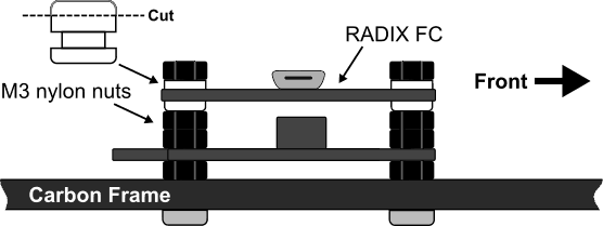
2: Installation with regular stacking height (6.5mm between boards):
If you don’t want to modify the 4-in-1 ESC and have enough vertical space, the RADIX FC can be stacked on top of the 4-in-1 ESC with a spacing of 6.5mm between the boards, which allows using the micor-SD card slot. To do so, first, use an knife to carefully cut the long side of the silicone grommets in the middle and put them with the short (uncut) side facing down on the RADIX FC. See notes above for tips on how to install the grommets. Second, put 4 additional nylon nuts on top of the nuts already installed, stack the RADIX FC. Finally, secure it using 4 nylon nuts. Don’t fasten the nuts too tightly, or they will squeeze the grommets and reduce their vibration isolation performance! The side view should look similar to this:
**Note that you can also use the silicone grommets unmodified with either the short side or the long side facing down. Doing so will increase the overall height of the stack, but if your frame offers enough vertical space, this may not be an issue.**
To complete the installation, connect the 4-in-1 ESC to the RADIX FC using the cable that is included with the RADIX FC (10-pin to 6pin/4pin connector):
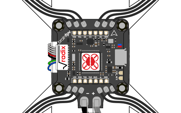
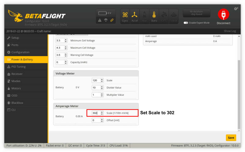
Finally, remember that the 4-in-1 ESC uses a different current sensor than the RADIX PB, so the default scale of “200” will give erroneous current measurements. When using the Hobbywing X-Rotor 40A 4-in-1 ESC, make sure to set the amperage meter scale to 302 in the Betaflight configurator:
Fixed Wing with RADIX Wing Power Board (wPB)
The RADIX flight controller is versatile and can be used for more than just quadcopters. With the RADIX Wing Power Board (wPB) you can use it on fixed wing aircraft (aka airplanes). When paired with our version of iNAV and a GPS receiver, it makes for great fixed wing flight controller with a beautiful graphical OSD. Below we walk you through the steps of building a flying wing with the RADIX wPB.
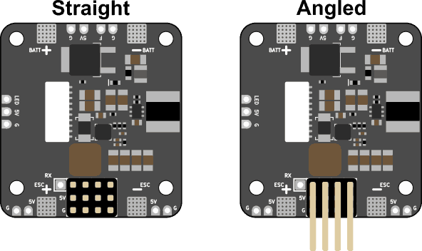
Install Servo Headers
The RADIX wPB can be used with either straight or angled servo headers. Both are included with the wPB. Use whatever works best for the airplane you are building. To install the servo headers, put them in place and solder the pins on the bottom of the wPB.
Powering Servos
Servos on fixed wing aircraft can draw quite a lot of current. The RADIX wPB has a 2A (3A burst) 5V regulator, which is enough for powering small servos. As a reference, the servos on a Nano Talon can be considered small and can be powered by the wPB, while the ones on a TBS Caipirinha 2 are too power hungry to be powered by the wPB.
To power the servos, you have 3 options:
- Power servos from the wPB: Simple, but only works for small servos.
- Power them from the ESC: Simple, servo size depends on ESC BEC.
- Power them from a separate BEC: Most reliable solution, servos still work if ESC fails.
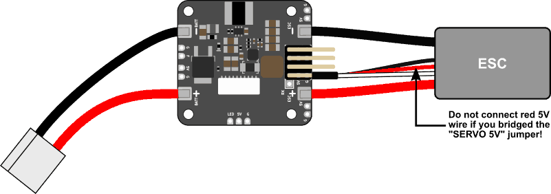
If you decide to power the servos using the wPB, use your soldering iron to bridge the “SERVO 5V” jumper on the bottom of the wPB.
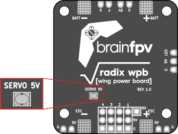
Remember: You can only have one 5V source connected at a time. So if you bridge the jumper and are using a ESC with a 5V BEC, you will need to remove the red 5V wire from the ESC connector.
Connect Battery and ESC
Connect the cable for the battery and the ESC (motor controller) as shown below. The wire gauge that should be used depends on your aircraft. For a small wing that draws less than 20A, you will be fine with 18 AWG, whereas for a very powerful wing you may want to use 12 AWG. The best bet is to use whatever your ESC comes with.
Connect Servos
To move the control surfaces of your aircraft, you need servos, obviously ;). How many you need depends on your aircraft; For a flying wing you only need 2 servos, whereas for a aircraft with aileron, elevator, and rudder, you may need 3 or 4. Connect the servos as shown in the iNAV mixer configuration when configuring your flight controller. For a flying wing, this means connect the servos to outputs 2 and 3 on the RADIX wPB.
The RADIX PB has 4 outputs and one of them is used for the ESC, which leaves space for 3 servos. If you need more servos, you can their signal wires to the S5 and S6 outputs of the RADIX FC. To power them, you will need to make a wire harness that connects their 5V and GND wires to the servo headers on the RADIX wPB.
Stack RADIX FC on top of wPB
The RADIX flight controller needs to be connected and stacked on top of the wPB. Follow the instructions for the regular PB above to do so.
Other Things
Programmable RGB LEDs: You can connect programmable RGB LEDs to the wPB. Read the instructions above on how to connect them. Keep in mind that the wPB can supply 2A total and that this current is shared with the flight controller, other 5V devices, and the servos (if you bridged the “SERVO 5V” jumper).
RX Pad: You may have noticed that the wPB has a “RX” pad next to output 1. This pad is connected to RX4 (UART4 RX) of the RADIX flight controller via the cable. This is intended for ESC telemetry, but this feature is not yet supported by iNAV.
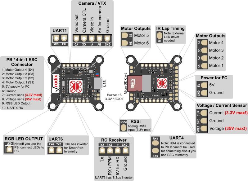
RADIX FC Quick Reference
Betaflight Quick Start Guide
Now that you have set up your RADIX System, it is time for you to configure the firmware.