Article sections
Introduction
This manual is for the RADIX 2 HD flight controller released in 2023. The RADIX 2 HD is an evolution of the legendary RADIX 2 flight controller. It uses the same blazing fast H7 processor and BMI270 gyro delivering unparalleled flight performance. With a plug-and-play connector for HD systems and dual 4-in-1 ESC connectors, the RADIX 2 HD is the best choice for building advanced FPV drones such as X8 cinelifters.
NOTE: If something is missing or unclear, don’t hesitate to contact us at support@brainfpv.com. We are happy to help!
Quick Reference
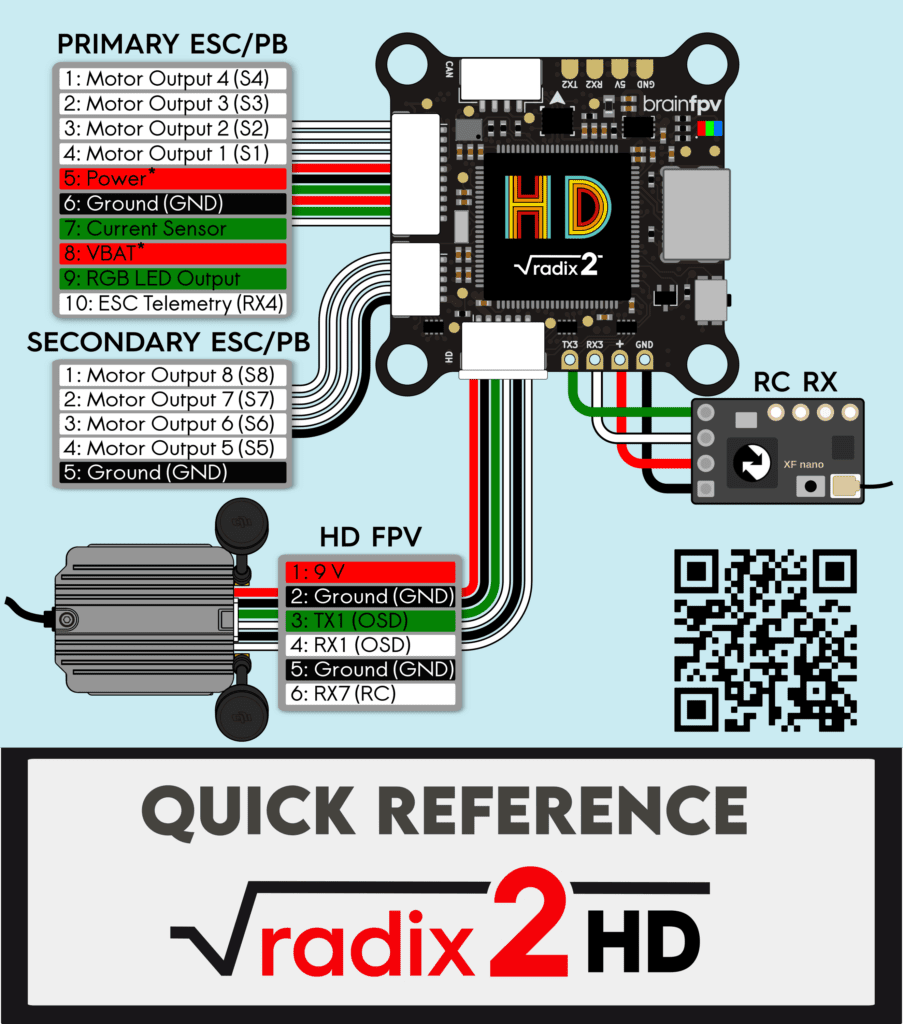
The Quick Reference is also included as a card with the RADIX 2 HD. It shows the pinout of the connectors for connecting the ESC’s, the HD system connector, and how to connect an RC receiver. Make sure to read the “Powering and Voltage Measurement” section on the second page.
 Pinout and Details
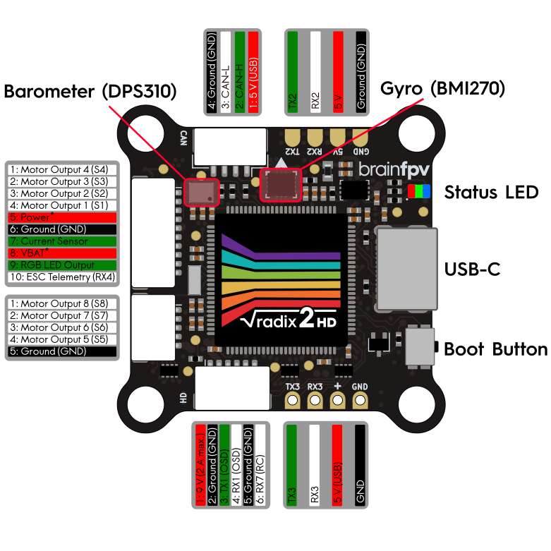
The diagram below shows the complete pinout of the RADIX 2 HD and the location of important components, such as the gyro, the barometer, and the “PWR:VBAT” jumper.
Installing Firmware
The RADIX 2 HD uses the BrainFPV bootloader for easy updating of the installed firmware. When the flight controller is in bootloader mode, it will appear as an external drive when connected to a computer and the firmware is updated by simply copying the firmware file to the drive. This has the advantage that no special drivers are needed for updating the firmware. See here for more details. Download firmware from here.
To get notified when a new firmware version is available, make sure to subscribe to the firmware update mailing list using the form below.
Install the RADIX 2 HD in your Drone
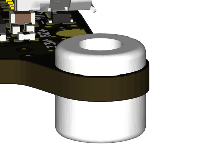
Before installing the RADIX 2 HD in your drone, insert the white silicone grommets that are included into each of the mounting holes in the corners. The long side of the grommet should face downwards (opposite side of the connectors).
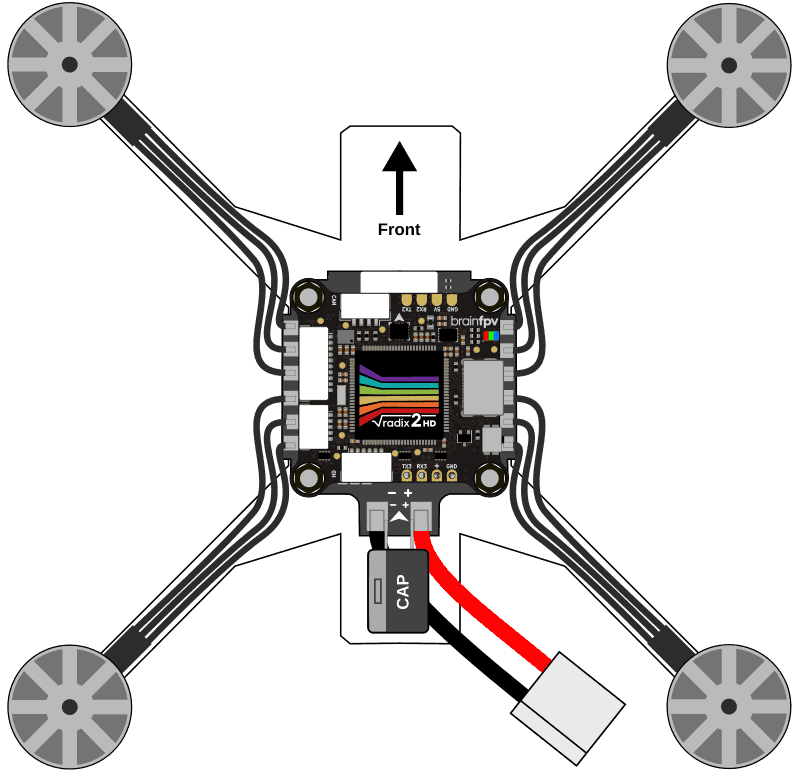
When installing the RADIX 2 HD in your drone, make sure the orientation is correct. I.e., the connectors should face upwards and the small white arrow in the front / center of the flight controller should point in the forward flight direction, as shown below. Note that it is possible to install the flight controller in a different orientation, but you will need to configure the orientation of the flight controller in Betaflight / INAV if you do so.
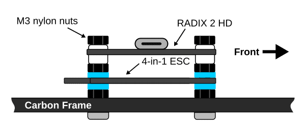
Also make sure you have adequate spacing between the carbon frame and the 4-in-1 ESC, and the 4-in-1 ESC and the RADIX 2 HD. If you have sufficient vertical space, we recommend adding additional nylon nuts between the components, as shown below. Without the additional nylon nuts, it is more likely that components get damaged during a crash when the silicone grommets get compressed and the 4-in-1 ESC touches the carbon frame or the RADIX 2 HD.
Connect 4-in-1 ESC
The RADIX 2 HD is compatible with all 4-in-1 ESC’s (electronic speed controllers) currently on the market. The included cable kit allows you to make a custom cable that will work with most 4-in-1 ESC’s. Refer to the RADIX 2 4-in-1 ESC connection manual for how to connect the RADIX 2 HD to your 4-in-1 ESC.
Connect RC Receiver
The RADIX 2 HD flight controller can be used with a large number of different RC receivers. Pretty much any serial receiver is supported. Older PPM and PWM receivers are not supported. Below you find instructions on how to connect the most commonly used receivers.
TBS Crossfire Receiver
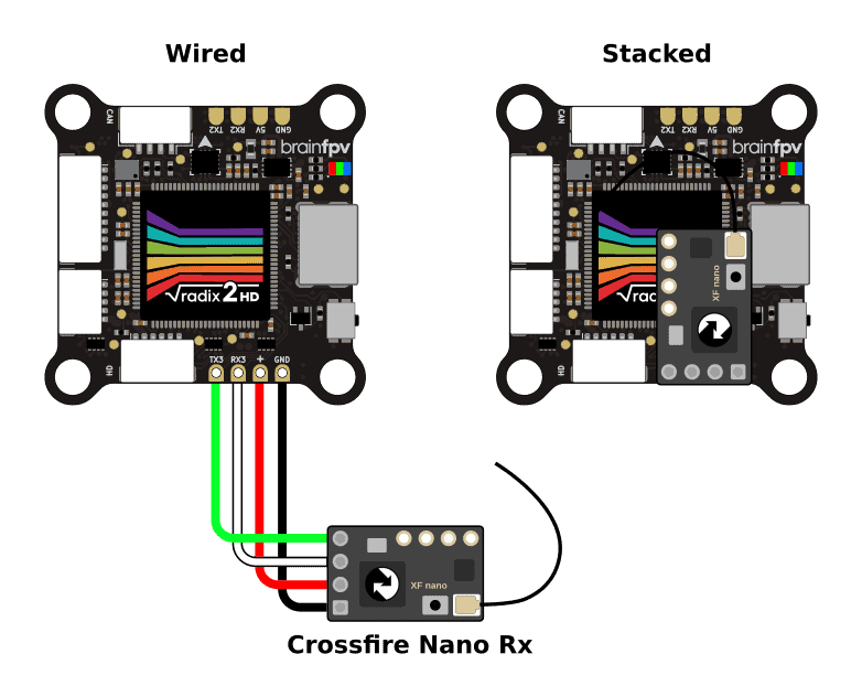
The Team BlackSheep (TBS) Crossfire system is a popular long-range system that operates on the 915 MHz / 868 MHz frequency band. When using a Crossfire receiver with the RADIX 2 HD, connect it as shown in the diagram below.
- Ground (GND): Connect to GND pad of RADIX 2 HD.
- Power: Connect to + pad next to RX3 of the RADIX 2 HD. This is a special 5 V pad that is also powered when your RADIX 2 HD is connected to USB. So you can configure your transmitter without connecting the battery to your drone.
- CH 1: Connect this wire to RX3 (UART3 RX). Make sure to set this output to CRSF TX when configuring the Crossfire system.
- CH 2: Connect this wire to TX3 (UART3 TX). Make sure to set this output to CRSF RX when configuring the Crossfire system.
You can either wire the Nano Rx to the RADIX 2 HD, or use the pins included with the Nano Rx to stack it on top and secure it using double sided tape. The Crossfire Diversity Nano Rx is connected the same way.
Note: If you are using the backup battery functionality of the Diversity Nano Rx, it will draw more current than a normal receiver when it is charging the battery. This may cause problems when the RADIX 2 HD is powered from USB, as your computer may disconnect the device if it draws too much current. In this case, you can power the receiver from a regular 5 V pad of the RADIX 2 HD.
TBS Tracer Receiver
The Team BlackSheep (TBS) Tracer system is a medium to long-range RC system operating on the 2.4 GHz band. The way it connects to the RADIX 2 HD and configuration of the is identical to the Crossfire receiver shown above.
ExpressLRS Receiver
ExpressLRS is a popular open source long range RC system. There are a wide variety of receivers from multiple manufacturers available. The ExpressLRS receivers use the CRSF protocol like the TBS Crossfire system. The wiring and configuration is identical to the Crossfire receiver shown above.
Immersion RC Ghost Receiver
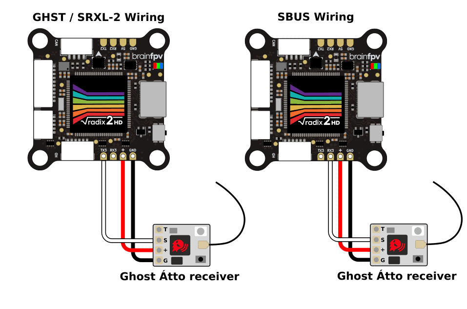
The Immersion RC Ghost system is a medium to long-range RC system operating on the 2.4 GHz band. The receivers can use different protocols. The preferred protocol is GHST which is supported by both Betaflight and INAV. Wire the receiver as shown below. Note that the signal wire connects to the TX3 pad of the RADIX 2 HD, not to the RX3 pad. Alternatively, the Ghost receivers can also use the SRXL-2 or SBUS protocol.
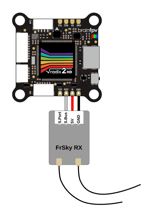
FrSky S.Bus / S.Port Receiver
The diagram below shows how to connect a FrSky S.Bus receiver to the RADIX 2 HD. The S.Bus wire carries the RC data and needs to be connected to RX3. Some FrSky receivers also have an S.Port wire / pad for telemetry information that allows it to send battery voltage, current draw, etc. back to your RC receiver. If your receiver features S.Port, connect it to TX6 on the bottom of the RADIX 2 HD. Note that you can also use a different TX pad of an unused UART (not RX3, as UART3 is used for S.Bus).
FrSky FPort Receiver
FrSky FPort is a receiver protocol that uses a single wire for both RC data sent to the flight controller and telemetry data sent back to your RC transmitter. The FPort signal needs to be connected to the TX3 pad of the the RADIX 2 HD, as shown below.
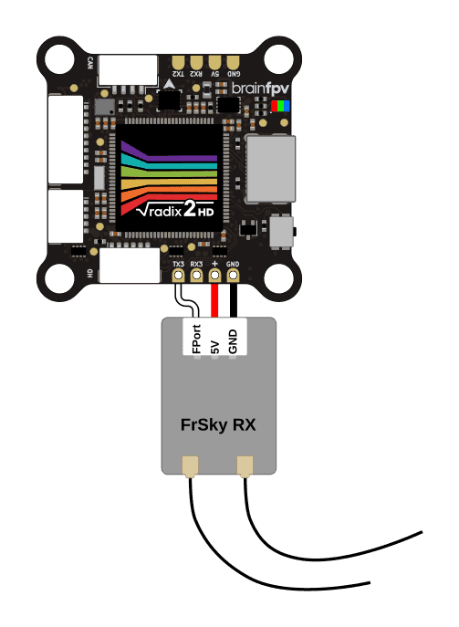
Make sure to set the receiver protocol to FPort and enter the following in the Betaflight command line (CLI) to make it work:
set serialrx_halfduplex = ON
set serialrx_inverted = ON
save
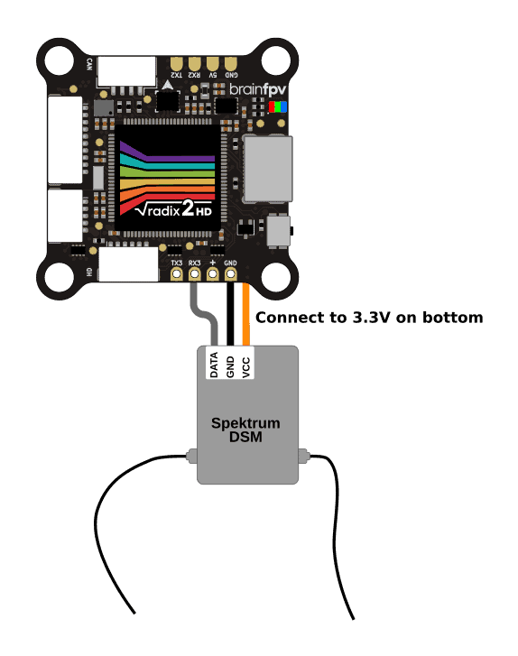
Spektrum DSM Receiver
If you use a Spektrum DSM or DSMX satellite receiver, connect it as shown below. Unlike pretty much every other receiver on the planet, the satellite receivers need to be powered using 3.3 V instead of 5 V, so make sure to connect the orange wire to the 3.3 V pad on the bottom of the RADIX 2 HD.
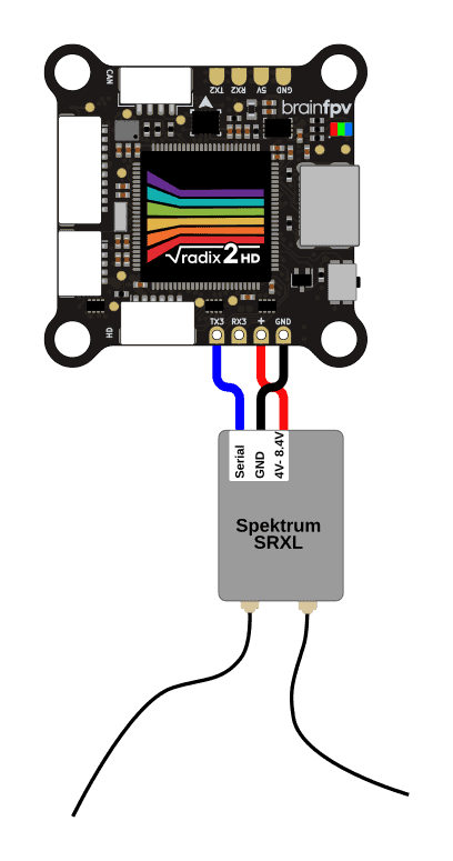
Spektrum SRXL / SRXL-2 Receiver
Some newer Spektrum receivers support the SRXL or SRXL-2 protocol and they can be powered from 5 V (amazing!). This RC protocol uses a single wire for both RC data and telemetry. The serial wire needs to be connected to the TX3 pad, as shown below.
Connect Digital (HD) FPV System
The RADIX 2 HD is designed to be compatible with all digital FPV systems currently on the market. It has a built-in 9 V / 2 A regulator to power the digital FPV system. Note that the 9 V output voltage will be about 1.5 V less than the battery voltage if the battery voltage drops below 10.5 V. If you use a 2S battery, we therefore recommend powering the HD system directly from the battery, as the output voltage from the 9 V regulator may be too low when the battery is fully discharged.
The HD system is connected to the RADIX 2 HD using the 6-pin connector at the back of the flight controller. The pinout of the connector is as follows (the color corresponds to the color of the cable included with the RADIX 2 HD):
- 9 V: Voltage to power the HD system. The voltage regulator can deliver up to 2 A.
- Ground (GND): Ground connection.
- TX1: Serial data output (UART1 TX) for sending data to the HD system.
- RX1 (white): Serial data input (UART1 RX) for receiving data from the HD system.
- Ground (GND): Ground connection.
- RX7 (white): Serial data input (UART7 RX) for RC receiver connection (only supported by some HD systems).
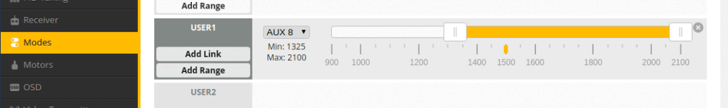
One problem with HD system is that they can get very hot when on the ground due to the lack of cooling from air flow. To prevent this, the RADIX 2 HD has a built-in “HD system pit switch” that allows you power off the HD system completely by turning off the 9 V regulator using a switch on your RC transmitter. To do so, configure the “USER1” switch in Betaflight / INAV as shown below.
Below we provide more details on how to connect some of the most popular FPV systems currently on the market.
DJI O3 Air Unit
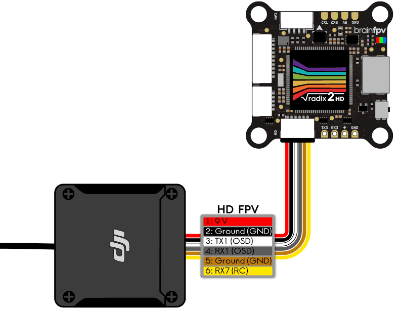
The DJI O3 Air Unit is the latest generation air unit for the DJI digital FPV system. The O3 Air Unit can be directly connected to the RADIX 2 HD using the cable that is included with the O3 Air Unit as shown below. Note that the cable colors correspond the colors of the cable included with the O3 Air Unit.
The O3 Air unit also provides RC receiver functionality when used with the DJI FPV Remote Controller 2. To use this feature, configure the RC receiver port to be UART7 in Betaflight / INAV and set the RC receiver protocol to SBUS.
DJI Air Unit
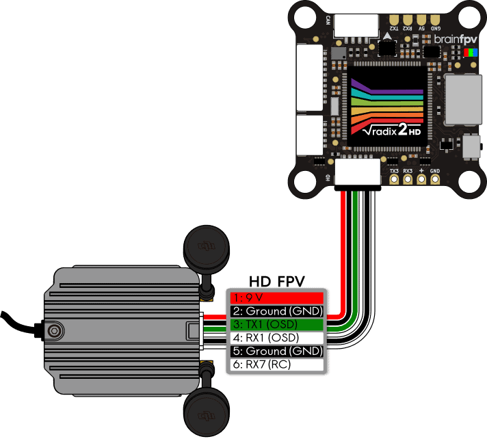
The DJI Air Unit was the air unit for the first generation DJI FPV system. It was later manufactured by Caddx and RunCam. The most recent versions have a cable included that can be directly connected to the RADIX 2 HD. Connect it to the RADIX 2 HD as shown below.
Note that the cable colors correspond to the colors of the cable included with the Air Unit sold in the BrainFPV shop, so the colors may be different for the cable you use. Just make sure that the wires connect 1:1, i.e., pin 1 goes to pin 1, pin 2 to pin 2, etc. As shown below.
HDZero Freestyle VTX
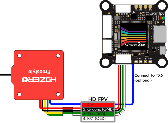
The HDZero system is a digital FPV system that has a lower latency than the DJI system and parts of the system are open source. HDZero offers a number of different video transmitters (VTX) for their system. How to connect the HDZero Freestyle VTX is shown below.
The VTX comes with a cable for the 5-pin “Power/UART Connector” connector of the VTX. Use this cable with the 6-pin cable that is included with the RADIX 2 HD to make a custom cable to connect the two. Note that only pins 1 to 4 of the HD connector of the RADIX 2 HD are used. The other 2 wires have been removed. The blue “Smart Audio” wire of the VTX can be connected to a UART TX pin of the RADIX 2 HD, e.g., TX6 on the bottom. Doing so lets you change the video transmitter frequency and power levels using “Smart Audio”.
Other HD Systems
There are a number of different digital (HD) FPV systems on the market that are not (yet) listed here. If your system is not listed, it will work as long as it can be powered from 9 V and it does not draw more than 2 A of current. To connect it, use the pinout of the 6-pin HD connector of the RADIX 2 HD at the start of this section together with the manual of your HD system. Typically, you will need 4 wires to connect it. I.e., the 9 V and ground (GND) connection and 2 serial wires (TX and RX) for sending on-screen display (OSD) and other data to the HD system.
Connect GPS Receiver
You can connect a Global Positioning System (GPS) receiver to the RADIX 2 HD. Having a GPS on board allows you to see the coordinates of your location in the OSD (very useful for finding your drone after a crash) and you can display the ground speed as well. In addition, you can use “GPS Rescue Mode” with Betaflight or Return-to-Home (RTH) with INAV for autonomously flying the drone back to you if for example the video malfunctions or if you lose connection between your RC transmitter and receiver. Note that this functionality is considered somewhat experimental and you should only rely on it after you have tested it several times and you are sure it works reliably.
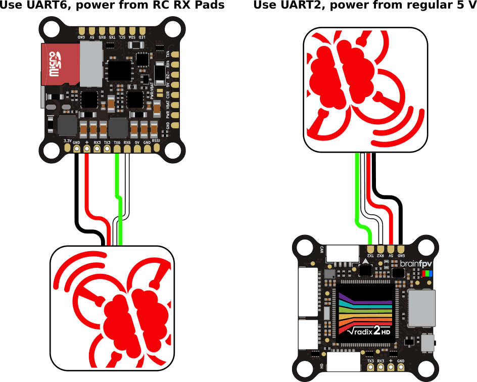
We recommend using the BrainFPV GPS, but any module with a uBlox chipset will work. Most GPS receivers need to be powered from 5 V and need to be connected to a serial port (UART RX / TX pair) of the RADIX 2 HD. The diagram below shows two options for how to connect the GPS:
- The GPS is connected to UART6 and powered from the receiver 5 V / GND pads (“+” and GND): By using the receiver 5 V pads, the GPS will also be powered when USB power is connected to the RADIX 2 HD. This can be convenient as it allows you to get a GPS lock without having to connect the battery by connecting a USB power bank to the RADIX 2 HD. Note that you will need to connect both the receiver and the GPS 5 V and GND wires to the same pair of pads of the RADIX 2 HD.
- The GPS is connected to UART2 and powered from regular 5 V: When using a regular 5 V pad to power the GPS, it will only be powered when the battery is connected to your drone.
Note that you can use any otherwise unused RX/TX pair (UART) to connect the GPS. UART6 and UART2 are just used as examples here.
Some GPS receivers also have an integrated magnetometer (compass). To use it, the compass needs to be supported by the firmware you are using. The SCL and SDA pads or wires of the GPS are the I2C bus that is used for the magnetometer data, they need to be connected to the SCL and SDA pads of the RADIX 2 HD (don’t cross the wires, i.e., connect SCL to SCL and SDA to SDA). Note that a compass is required for Return-to-Home (RTH) and other autonomous navigation capabilities with INAV, but is not needed when using “GPS Rescue Mode” with Betaflight.
Connect Buzzer
You can connect a 5 V buzzer to the RADIX 2 HD. The buzzer is useful for indicating warnings and also for locating your drone when you crash in tall grass etc. Any DC (direct current) 5 V buzzer should will work. The current drawn by the buzzer should be less than 200 mA, which should be the case for pretty much every buzzer sold for drones. Note that modern ESC’s can use the motors to buzz, which is maybe not as loud as an actual buzzer, but loud enough for locating your drone. So installing a buzzer is optional, as long as you setup the motors to be used as buzzer, or if you don’t want a buzzer at all and risk losing your precious drone ;).
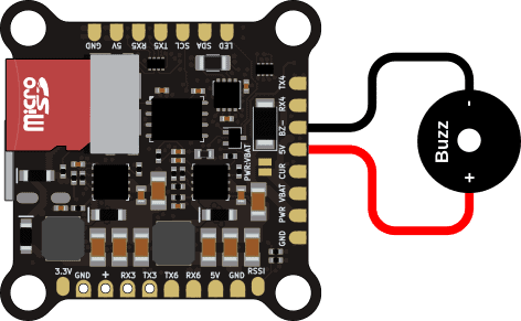
If you use a buzzer, wire it as follows shown below. The buzzer + pad needs to be connected to a 5 V pad on the flight controller. The buzzer – pad to the BZ- pad. When the buzzer is activated, the flight controller ties the BZ- to ground using a FET, which activates the buzzer.
Connect Servos
Its is possible to connect servos to the RADIX 2 HD, which allows you to for example tilt the FPV camera during flight. If you use a quadcopter or hexacopter, you can use the outputs S7 and S8 for servos. If you use an octocopter, you can re-configure the UART6 pins (TX6 and RX6) to be used for servos.
Configure Servos in Betaflight
When using Betaflight, enable the “SERVO TILT” feature to use servos. After that, you need to remap the outputs using the CLI commands below.
To use outputs S7 and S8 for servos, use the following CLI commands:
resource MOTOR 7 NONE
resource SERVO 1 D13
resource MOTOR 8 NONE
resource SERVO 2 D14
save
If you are building an octocopter and you are already using S7 and S8 for motors, you can use the TX6 and and RX6 pins for servos instead:
resource SERIAL_TX 6 NONE
resource SERVO 1 C06
resource SERIAL_RX 6 NONE
resource SERVO 2 C07
save
Configure Servos in INAV
When using INAV, no CLI commands are needed. When you are building a multi-rotor and add a servo to the mixer, it will automatically use S7 for the first servo if you use fewer than 8 motors, or TX6 if you are building an octocopter.