Article sections
The RADIX LI wing power board (wPB) was originally designed to be used together with the RADIX LI flight controller. This guide shows you how you can combine it with the RADIX 2 or RADIX 2 HD flight controller. Doing so gives you a compact flight controller stack for fixed-wing applications (airplanes), with the following features:
- All the features of the RADIX 2 (HD) flight controller.
- A servo header for connecting up to 6 servos.
- A separate 5 V / 3 A voltage regulator for powering the servos. If you want a higher servo voltage or need more current, you can also use a separate BEC.
- Accurate battery current measurement supporting up to 50 A constant, 60 A burst.
Note that one limitation is that the RADIX LI wPB only supports up to 5S (22 V). Therefore, while the RADIX 2 (HD) supports up to 8S, the maximum battery voltage is 5S when used together with the RADIX LI wPB.
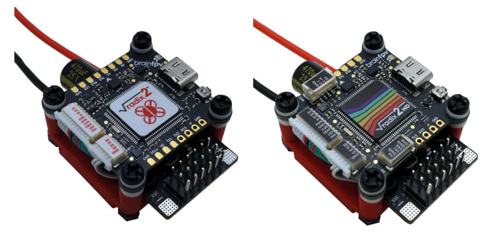
As the RADIX 2 (HD) flight controller and the RADIX LI wPB use different mounting hole spacings (30.5 mm and 20 mm, respectively), a 3D printed mount is needed to stack the flight controller on top of the wPB. If you have a 3D printer, you can download the files and and print the mount yourself. Alternatively, you can get one from our store. The photos below show the RADIX 2 and the RADIX 2 HD stacked on top of the RADIX LI wPB using the mount.
The 3D printed mount consists of two parts (top and bottom) and you also need 8 M3 nylon nuts, 4 M3 x 20 mm nylon screws, and 4 M3 x 8 mm nylon screws.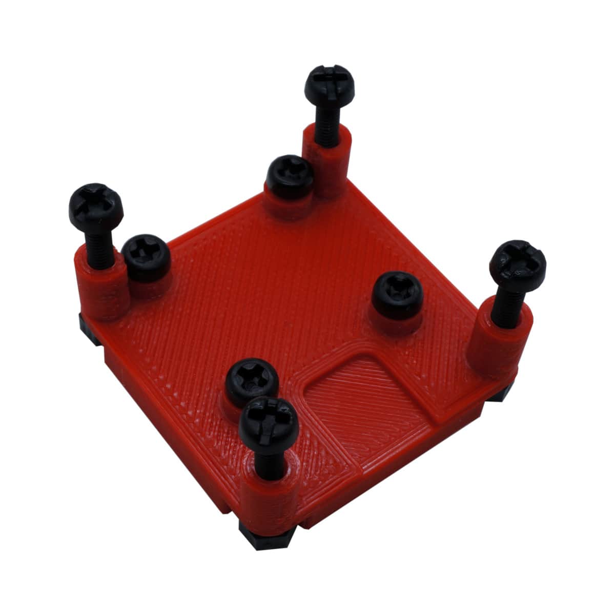
Install Servo Headers
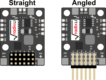
The wPB can be used with either straight or angled servo headers. Both are included with the wPB. Use whatever works best for the airplane you are building. To install the servo headers, put them in place and solder the pins on the bottom of the wPB.
Powering Servos
Servos on fixed wing aircraft can draw quite a lot of current. The RADIX LI wPB has a 3 A, 5 V regulator, which is enough for powering small servos. As a reference, the servos on a Nano Talon can be considered small and can be powered by the wPB, while the ones on a TBS Caipirinha 2 are too power hungry to be powered by the wPB.
To power the servos, you have 3 options:
- Power servos from the wPB: Simple, but only works for small servos.
- Power them from the ESC: Simple, servo size depends on ESC BEC.
- Power them from a separate BEC: Most reliable solution, servos still work if ESC fails.
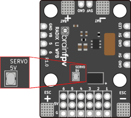
If you decide to power the servos using the wPB, use your soldering iron to bridge the “SERVO 5V” jumper on the bottom of the wPB.
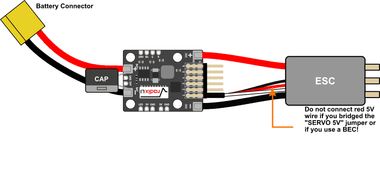
Connect Battery, ESC, and Capacitor
Connect the cable for the battery and the ESC (motor controller) as shown below. The wire gauge that should be used depends on your aircraft. For a small wing that draws less than 20 A, you will be fine with 18 AWG, whereas for a very powerful wing you may want to use 12 AWG. The best bet is to use whatever your ESC comes with.
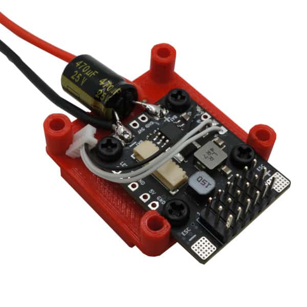
The RADIX LI wPB also includes a capacitor (“CAP”) that helps with reducing motor and ESC noise. Depending on how you power your video transmitter and FPV camera and on how good their noise filtering is, you may not need the capacitor. If you decide to install the capacitor, solder it in parallel with the battery, as shown below. Pay attention to the polarity of the capacitor; the band indicates the negative side that needs to be connected to “BAT -”
Solder the “PWR:VBAT” Jumper of the Flight Controller
The RADIX 2 (HD) flight controller has a “PWR:VBAT” connector on the bottom, which allows using the “VBAT pin” (pin 8) of the 10-pin connector for both powering the flight controller and for battery voltage measurement. When using the flight controller with the RADIX LI wPB, it is necessary to solder the jumper.
Install the RADIX LI wPB onto the Mount
Use the 8 mm screws to mount the wPB onto the 3D printed mount as shown in the photo below. Note that we also soldered the wires for outputs 5 and 6. This is only necessary if you need more than 4 outputs. To make the connection, use the 5-pin wire harness included with the flight controller and remove the first two wires from the connector (use tweezers or a knife to lift the tab on the bottom of the connector and then pull out the wire). Then cut off the crimp contacts and solder the wires to the solder pads as shown below. Note that we also soldered the ground (GND) connection, which isn’t strictly necessary but is recommended as it doubles up the ground connection between the flight controller and the wPB.
Install the Flight Controller onto the Mount
Connect the flight controller the the wPB using the short 10-pin wire harness that is included with the wPB. Then mount the flight controller onto the mount using the 20 mm screws.
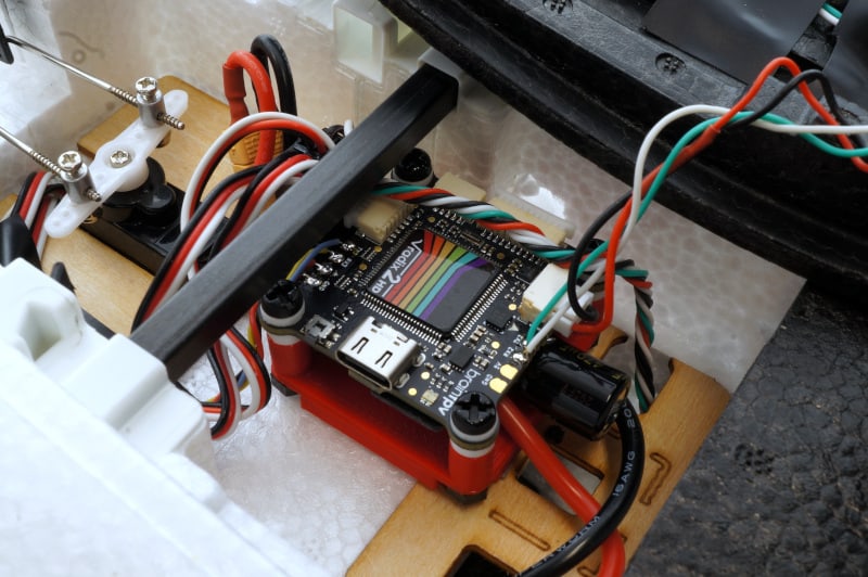
Install the Assembled Flight Controller Stack in your Plane
Finally, mount the stack in your airplane using double sided tape. Depending on the installation location, you may want to first connect other components, such as the RC receiver, GPS, video camera, etc. Refer to the RADIX 2 Manual or the RADIX 2 HD Manual for details.
Note that in the photo below, the GPS is connected to UART2 (the RX2 and TX2 pads). The 5 V and GND signals are connected to the CAN bus connector. This trick means that the GPS is also powered via the USB connector, which is convenient as it allows using the GPS without having to connect the battery. Alternatively, you can also use the 5 V and GND used for the RC receiver (“+” and GND pads next to RX3), which are also powered from USB. Using UART2 for GPS is also recommended as it is the default setting when the RADIX 2 HD is used with ArduPilot.
Configure the Current Sensor
The current sensor of the RADIX LI wPB is designed to provide accurate measurements of currents that are typical on small to mid-sized airplanes. The maximum current is 50 A constant and 60 A burst. To get the correct current scaling in your flight controller firmware, it is necessary to configure the scaling:
- INAV: Set the “Current Meter Scale” to 500 (which means 50 mV/A). This setting is in the “Configuration” tab under “Voltage and Current Sensors”.
- ArduPilot: Set “Amperes per volt” to 20. This setting is in the “Setup Tab” under “Battery Monitor” in Mission Planner.