Article sections
This guide shows you how to connect 4-in-1 motor controllers (ESCs) to the BrainFPV RADIX 2 and the BrainFPV RADIX 2 HD flight controller. The RADIX 2 (HD) comes with a wire kit that allows you to make a cable that works with any 4-in-1 ESC available on the market today. We first explain what connections are needed and how to insert the cables into the connectors. Finally, we provide wiring examples for some popular 4-in-1 ESC choices.
Flight Controller – 4-in-1 ESC Connections
Every 4-in-1 ESC currently available has the following connections:
- Motor Signals (S1 .. S4 or M1 .. M4): These connections are used to send RPM commands (how fast the motor should spin) from the flight controller to each ESC. With bi-directional DSHOT, the same wire is also used by the ESC to send RPM information back to the flight controller.
- Ground (GND): The ground reference voltage is always needed. On the ESC side, this is typically just connected to the negative battery pad (battery -).
- VBAT (BAT+): This is typically the full battery voltage. It is used for powering the flight controller and devices connected to it, as well as for battery voltage measurement. On the ESC side, this is just connected to the positive battery pad (battery +).
The 4-in-1 ESC may also have the following other connections that are not required, but will give it additional features:
- Current Sensor (CRT, CUR): This is the output of the current sensor on the 4-in-1 ESC that allows the flight controller to measure the current draw. The output is a voltage that is proportional to the current. The scaling depends on your 4-in-1 ESC and needs to be configured in the flight controller software (“current scale” in Betaflight) for the current reading to be accurate.
- ESC Telemetry (TLM): This is a serial signal for ESC telemetry, which can send information (current draw, voltage, RPM) to the flight controller. On the flight controller side, this signal is connected to a serial port (UART) RX pin/pad. Note: For ESC’s with an analog current sensor, ESC telemetry has limited usefulness, as the analog current sensor is typically more accurate. Also, the motor signals (S1 .. S4) are used to send RPM information to the flight controller at a higher rate than possible with ESC telemetry when bi-directional DSHOT is used. Therefore, we recommend not connecting / using the telemetry features for 4-in-1 ESC’s with a current sensor output.
- 5V / 10V: Some 4-in-1 ESC’s have built-in voltage regulators that can be used to power the flight controller and other devices. E.g. the original RADIX (F4 based) flight controller needed 5 V from the 4-in-1 ESC to be powered. The RADIX 2 has its own 5 V regulator and these connections are not needed.
RADIX 2 (HD) Primary and Secondary ESC Connections
The RADIX 2 (HD) features a 10-pin and a 5-pin connector for connecting a primary 4-in-1 ESC and a secondary 4-in-1 ESC when building octocopters with 8 motors. The pinout of the connectors is shown in the following diagram:
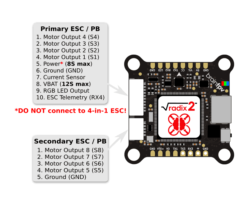
Following the description of the ESC signals above, the following signals need to be connected to your primary 4-in-1 ESC:
- Motor Outputs (S1 .. S4, pins 1 .. 4): Connect to the corresponding motor pins of your ESC.
- Ground (GND, pin 6): Connect to the ground pin of your ESC.
- VBAT (pin 8): Connect to VBAT pin of your ESC. Make sure to solder the “PWR:VBAT” jumper of your RADIX 2 (HD) to also power the RADIX 2 (HD) from this pin. See the RADIX 2 Manual or the RADIX 2 HD Manual for details.
If supported by your ESC, you can also connect the following signals:
- Current Sensor (pin 7): Connect to current sensor pin of your ESC.
- ESC Telemetry (pin 10): Can be connected to the telemetry output of your ESC. Note: This connection is optional and is of limited use, see notes above. If you connect it, you can’t use UART4 of the RADIX 2 (HD) for other features, as it is connected to the ESC.
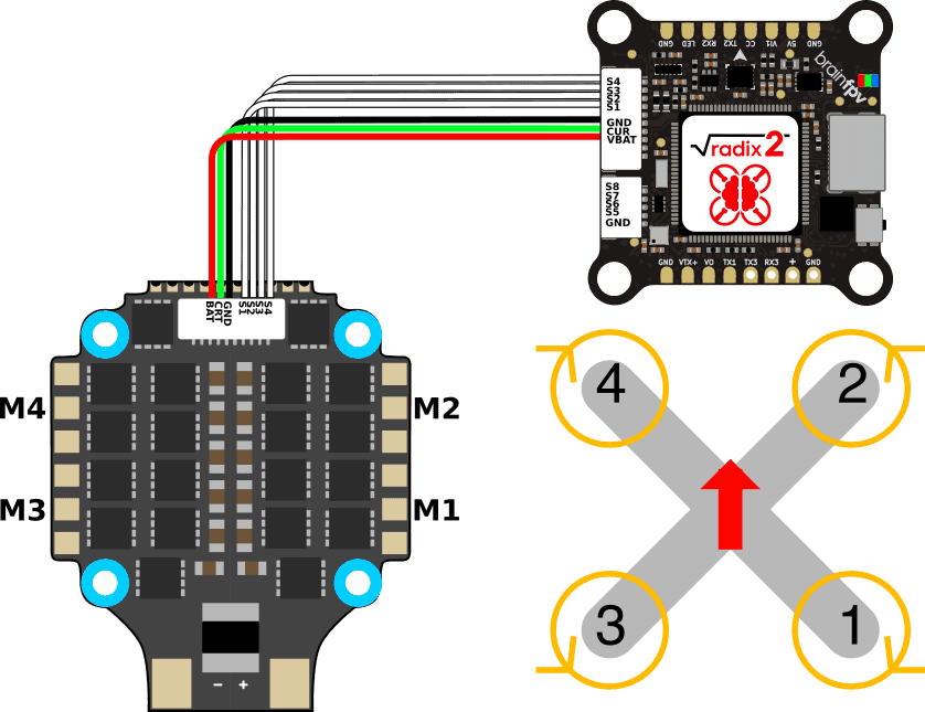
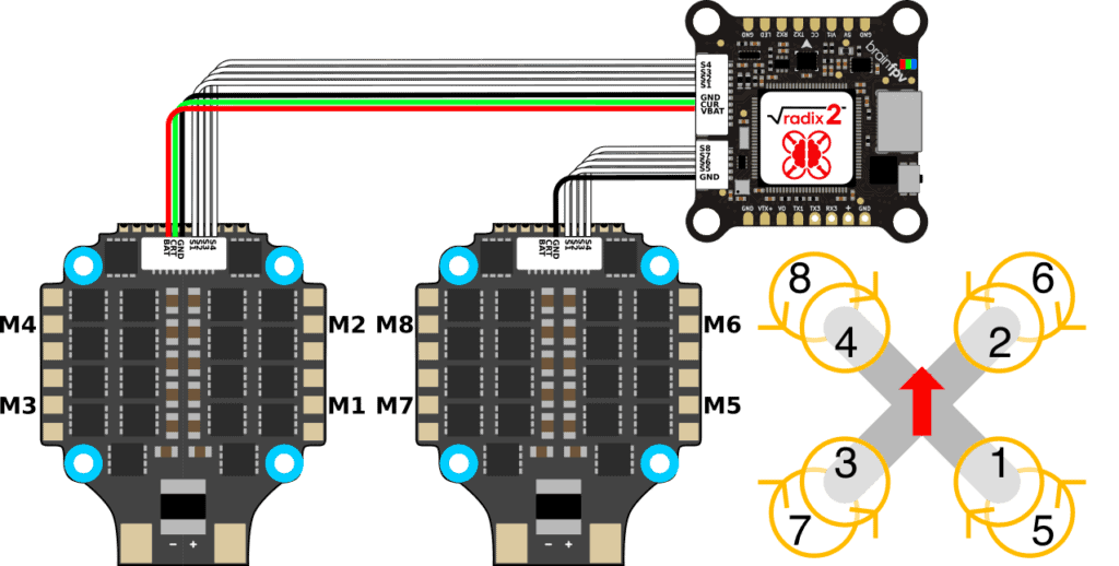
Example: Quadcopter using Primary ESC Connection
The diagram below shows how to connect an Hobbywing “XRotor FPV G2 ESC (4in1) 65A” ESC when building a quadcopter. It also shows the motor order and directions that are default in Betaflight and INAV. For more details about using this ESC, see below.
Example: Octocopter using Primary and Secondary ESC Connections
If you are building an ocotocopter, also connect the motor signals S5 .. S8 and the ground connection to the second ESC as shown below.
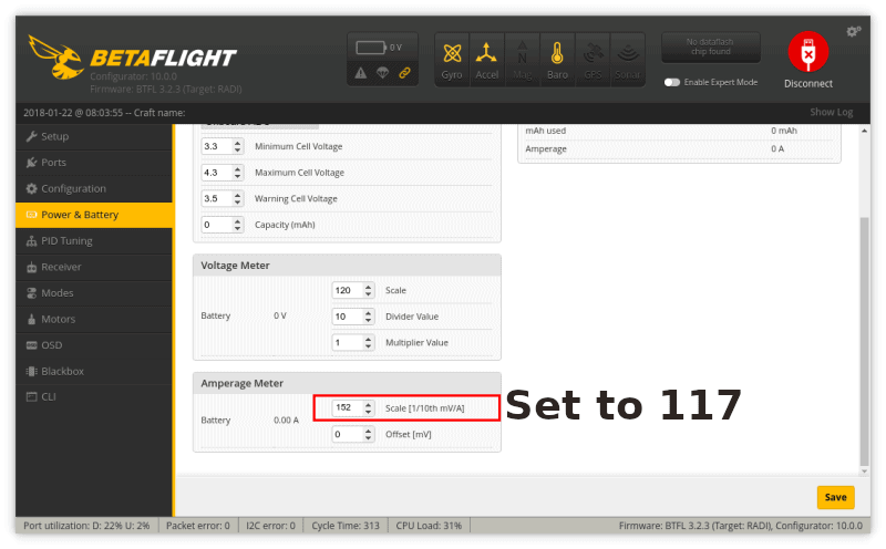
Note that when using this setup, the current measurement is only provided by one ESC. So the flight controller will not be measuring the total current draw. A trick you can use to get a more accurate current measurement is to double the measured current from the first ESC. To do so, divide the “current meter scale” in the flight controller configuration by 2. E.g., for the Hobbywing “XRotor FPV G2 ESC (4in1) 65A” ESC the scale should be 117, so use 117 / 2 = 59 (rounded).
Making an ESC Wire with the RADIX Spare Parts Kit
The RADIX 2 (HD) comes with a spare parts kit that includes a 10-pin connector with some wires inserted, empty 10-pin, 8-pin, and 7-pin connector housings for the ESC side. In addition, it also comes with a 5-pin connector with wires inserted for the secondary ESC connection.
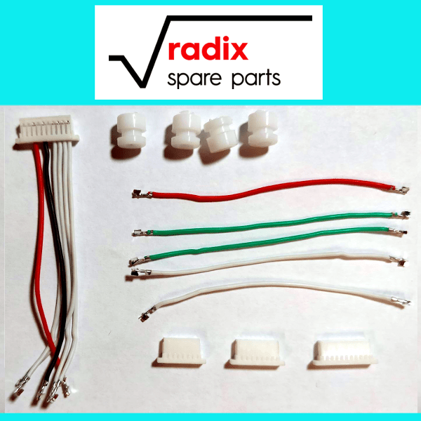
To make a custom cable for your 4-in-1 ESC, use either the 10-pin, 8-pin, or 7-pin connector housing and insert the crimped wires at the correct locations. See below for popular ESC choices and the information above if your ESC is not listed. The 10-pin connector on the flight controller side already has the motor signal (S1 .. S4), the ground, and the VBAT wires inserted at the correct locations. You will need to add additional wires if your ESC features a current sensor output, or if you decide to connect ESC telemetry.
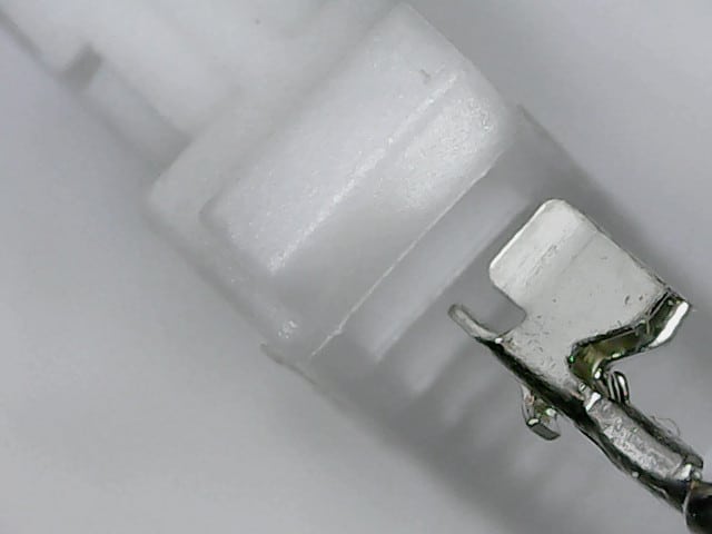
When inserting the wires into the connector housing, make sure that the hook of the crimp contact faces the bottom of the connector. The bottom is the side with the little tabs that hold the contacts in place. If you accidentally insert a contact at a wrong location, use an knife of tweezers to carefully lift the tab and pull out the contact. Make sure to not bend the tab too much, as it won’t securely hold the contact if you do so.
Wiring Examples For Popular ESC Choices
Below is a list of wiring examples, as well as the current sensor scaling for popular ESC choices.
Note: This information if only provided as a reference. Always follow the documentation provided with your ESC, as manufacturers may change the pinout when they make a new revision of their product.
Hobbywing XRotor FPV G2 ESC (4in1) 65A and XRotor Micro 4-in-1 60A ESC
The Hobbywing 4-in-1 ESC’s are some of the most reliable ESC’s on the market. The latest version is the “XRotor FPV G2 ESC (4in1) 65A“. It uses the BLHeli 32 firmware, so you get features like bi-directional DSHOT for RPM based adaptive filtering, supports up to 6S batteries and up to 65 A (80 A burst) of current per motor. The ESC also has an analog current sensor for current measurement. The diagram below shows how to connect the ESC. Note that in addition to the wires that were already inserted into the 10-pin connector, we used a green wire for the current sensor.
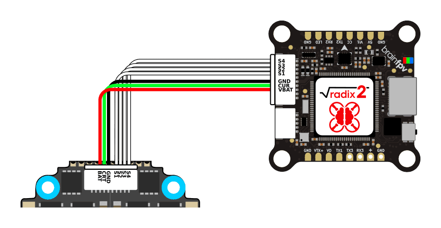
Note: The pinout of the ESC is almost identical to the one of the RADIX 2. You can use the wire that comes with the ESC that has 10-pin connectors on each side. But make sure to remove the wires of pins 5, 9, and 10. So you get a wire as shown above. Leaving them connected will damage your RADIX 2 (HD) and potentially also your 4-in-1 ESC.
The current sensor scaling for the ESC is 11.75 mV/A (so the ESC will output 11.75 mV for each Ampere of current that it draws). This means the current meter scale in Betaflight needs to be set to 117: