“This is what it means to be using BrainFPV products; you will always be using the latest technology that will then be adopted throughout the industry (by which time we’ve already moved to the the next great thing).”
By now, you may have noticed, BrainFPV has a new website! We completely scrapped the old site and started from scratch. We hope you like the result. Make yourself at home.
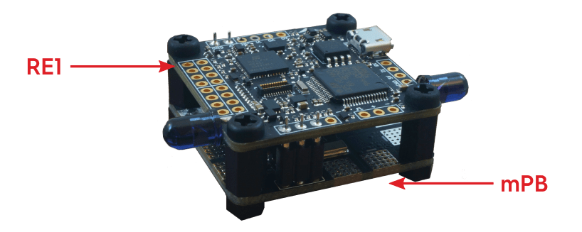
Our website is not the only thing that’s shiny and new over here at BrainFPV. We are proud to announce two exciting new products: BrainFPV RE1 (Racing Edition 1) flight controller and its companion product, Mini Power Board (mPB).
We did our best to keep things as simple as possible, so there is no unnecessary wiring between components and the setup is straightforward while still giving you a lot of options. We are thrilled about it (get ready to happy dance) and think you’ll love it.
THE JOURNEY: From BRAIN to RE1
We thought it would be fun to invite you behind the scenes at BrainFPV and share some details about the development of RE1 and the engineering decisions behind it.
The original (last generation) “Brain” flight controller was released at the end of 2014. While the design of Brain was solid , we learned a lot and were eager to make improvements. Below are a few examples of what we have been working on over the past year. OK, let’s get nerdy!
1. JST-SH Connectors
- What we wanted to improve: It turns out most people don’t like JST-SH connectors. While they are pretty neat in terms of PCB real-estate required, they are a bit of a pain to work with due to the tiny connectors. The connectors also don’t lock, so there is the possibility of a connector unintentionally becoming loose. So yeah, we won’t be including those in the RE1.
- Solution: Naturally, not using JST-SH connectors was easy but dropping the connectors means the space on the board gets tight if we use the same number of connections with regular servo headers. Therefore, we decided to remove support for PWM receivers, which need a separate signal for each channel and therefore a lot of board space. In addition, we removed the 5V power pin from the servo headers, which aren’t needed when connecting motor controllers (ESCs) with only the signal and ground connections to the flight controller. Problem solved. Next.
2. Accelerometer / Gyroscope Sensitive to Vibrations
- What we wanted to improve: To the best of our knowledge, Brain was the first flight controller to use the Invensense MPU9250 accelerometer / gyroscope / compass. While this sensor performs quite well and has been adopted by numerous flight controllers since then (OpenPilot Revo Nano, Sparky2, Pixracer, SP Racing F3 Mini / EVO, to name a few), we have found that vibrations can negatively affect the measurements. While this problem usually can be alleviated using some form of vibration damping, modern racing quadcopters usually have very little space for mounting the flight controller and it can therefore be difficult to achieve sufficient damping of vibrations. We had a fun time figuring out a way to solve this problem.
- Solution: Finding an alternative for the MPU9250 was challenging. We evaluated a number of sensors from different manufacturers and finally selected the BMI160 from Bosch Sensortec. One advantage of the BMI160 is that it can run faster than the MPU9250 while still using the internal antialiasing filters. In our tests we found that it is much less sensitive to vibrations. Like with the MPU9250 in Brain, RE1 is the first flight controller to use this sensor and we expect it to be widely used in drone racing flight controllers in a year from now. This is what it means to be using BrainFPV products; you will always be using the latest technology that will then be adopted throughout the industry (by which time we’ve already moved to the the next great thing).
3. SPI Connections for Sensors and OSD
- What we wanted to improve: Due to the way the On-Screen Display (OSD) on Brain worked, it was necessary to use two SPIs (Serial Programming Interfaces), which are fast serial interfaces for connecting peripherals to a microcontroller, for the OSD. Therefore, the MPU9250 sensor had to be connected a slower I2C interface, which is typically about 10 times slower than SPI and also creates more processing overhead. This put some limits on how fast the sensors could be read out, which meant the sensor couldn’t be read faster than 1kHz. Note that 1kHz is already quite fast but due to the filtering employed in the MPU9250 there is a possibility of aliasing, which is undesired.
- Solution: Unlike in Brain, which used I2C for the sensors, the RE1 uses the BMI160, that’s connected to the microcontroller using a dedicated SPI interface, guaranteeing the lowest possible latency and high sampling rates. We used a second SPI for FLASH memory and the RE1 extension port (for connecting future accessories). This created the challenge of finding a way to attach the OSD using only a single SPI. This required us to completely re-engineer the circuitry that overlays the OSD on top of the video feed. Not a piece of cake, let me tell you. In the end, we decided to create our own digital OSD design implemented in an FPGA, which is a programmable digital logic device. The FPGA receives video overlay data from the microcontroller using a QUADSPI interface, which is similar to a normal SPI but can support higher data transfer rates. Apart from the OSD, the FPGA is also used for additional functions in RE1, such as inversion of serial signals, control of programmable RGB LEDs (so you can add some bling to your drone), and sending of infrared (IR) data for lap timing systems. It took us a long time to implement. A long time. In the end, it turned out better than we imagined.
RE1 OSD Development
4. Confusing Receiver Options and Limitations
- What we wanted to improve: When designing Brain, we wanted to give the user as many options as possible. This lead to some confusing options. For example, Brain had an “RxPort”, which could only support PWM and PPM receivers. Serial receivers, such as S.Bus or DSM, had to be connected to a serial port with some additional limitations, e.g., S.Bus was only supported on one serial port and DSM binding on the other. Moreover, the number of available PWM outputs (to connect motor controllers) also depended on the selected receiver, .e.g., when a PWM receiver was used only 4 outputs were available while up to 10 could be used with a DSM or S.Bus receiver.
- Solution: For RE1, we wanted to keep things simple and have one port that works with all receivers supported. There is also a selectable voltage for the receiver (5V or 3.3V) and the receiver is powered when RE1 is connected to USB. This makes setup and more straightforward and safer, as the receiver can be setup without having to connect the main battery, so there is no danger of having the motors unintentionally turn on during this step. In addition, RE1 always has 6 PWM outputs available on the same pins, which makes it even easier to use. Boom.
5. Bonus Material: Faster Processor
To cope with the higher processing requirements due to the faster (1.6kHz) sampling rate of the BMI160, we upgraded the processor to the latest generation STM32 F4 chip that can can run at 180MHz (compared to 168MHz on Brain).
Fun fact: This is also a first. Currently, there are no other STM32 F4 based flight controllers that run as fast as RE1. The high speed guarantees that the flight controller will be able to run advanced flight control code with ease.
6. Price
Given the capabilities of the Brain - there is still nothing comparable on the market, we think the price was fair, however A number of people were turned off by the price of the Brain, which was ($129 when it was first released and $99 later on). So, we really wanted to challenge ourselves and set off to make RE1 more affordable.
How could you possibly make the RE1 better AND cheaper, you ask? We have no idea. But we actually did it! The MRSP of RE1 is $79. While we aimed at making RE1 affordable, we refuse to make it cheap.
7. Quality and Open Source
As you know, there are loads of cheap flight controllers available. Our aim is for RE1 to be the best racing flight controller, not the cheapest. We also refuse to cut corners by lowering the quality. Therefore, we decided to assemble RE1 locally in the United States with a company that specializes in complex assemblies for major defense and medical device companies. Our quality control procedure also includes a full functional test, so we can be really sure that each RE1 is as good as the next.
Lastly, it is worth noting that with purchasing our products, you are not only supporting hardware development, you are also supporting open source software development. For example, some of our contributions to dRonin are directly related to RE1. E.g.: support the STM32F446 (#144, #742), driver for BMI160 (#743), optimization of the stabilization / actuator system (#758), code to generate I-Lap and Trackmate IR transponder packets (#963), and the addition of a new pixel format and driver for the OSD (#964). These contributions not only benefit us, but also other flight controllers using dRonin and the open source flight controller community as a whole.
Hopefully, by now you are thinking “When and where can I get a RE1?” and the answer is soon! Check out our next post for timeline details.
Thanks for joining us behind the scenes at BrainFPV and hope we didn’t bore you with too many technical details. Moving forward, we will regularly be publishing blog posts on a variety of drone related topics. We love to share our passion for drones with you and are planning for some informative and educational blog posts, enabling our readers to stay on top of the rapidly evolving world of drone technology.
Feel free to leave a comment below with your thoughts and perhaps suggestions for future blog post topics. And make sure to sign up to our mailing list to be notified when pre-orders start.
FLY ON,
Martin Luessi, Founder / CEO BrainFPV

Hi,
I have the old BrainFPV, and I need the squemes that you had in the web page and all the information for connectios Please.
Thanks a Lot
Please excuse the oversight. The old support pages can be found here: http://wwwold.brainfpv.com/support/ we will keep this up until the content has been migrated to the new website.
I have the old Brain. Save pages with information about it!
Your quote
“To cope with the higher processing requirements due to the faster (1.6kHz) sampling rate of the BMI160, we upgraded the processor to the latest generation STM32 F4 chip that can can run at 180MHz (compared to 168MHz on Brain).
Fun fact: This is also a first. Currently, there are no other STM32 F4 based flight controllers that run as fast as RE1. The high speed guarantees that the flight controller will be able to run advanced flight control code with ease.”
My $37 CC3D Revo F4 is running 192MHz.
# RaceFlight 16.04.24c – RaceFlight Release 1 RC12 – Buttered Razors. /REVO_OPBL Apr 25 2016
# status, System Uptime: 26 seconds, Voltage: 0 * 0.1V (3S battery – OK), System load: 0.23
CPU Clock=192MHz, GYRO=MPU6000, Cycle Time: 124, I2C Errors: 0, config size: 1856
# tasks
Task list:
0 – SYSTEM, max = 2 us, avg = 0 us, total = 0 ms
1 – GYRO/PID, max = 1140 us, avg = 106 us, total = 26369 ms
3 – SERIAL, max = 94 us, avg = 0 us, total = 3 ms
4 – BEEPER, max = 3 us, avg = 0 us, total = 1 ms
6 – RX, max = 55 us, avg = 1 us, total = 37 ms
What gyro read, pid loop, and esc write freq does this board run at?
Thanks
The stabilization chain (gyro, PID loop, ESC output) all run at 1.6kHz. In dRonin, the chain is triggered by the gyro interrupt, so everything is nicely in sync.
That your CC3D Revo F4 can run at 192MHz is interesting. The STM32F405 on your board supports 168MHz max, so you are overclocking the chip. This is not something that I would recommend doing unless you understand the potential consequences, i.e., erroneous behavior, overheating, premature failure.
PS: “CC3D Revo” is a name invented by the clone manufacturers. OpenPilot never had such a board, there was CC3D (F1 based) and Revolution (F4) based. A clone board will always be cheaper, as those companies invest 0 in hardware and software development, have poor quality control, no customer support, etc.
So, is there any harm in flashing my BrainFPV with RaceFlight using the Sparky2 settings? (other than loosing the OSD)
This won’t work and will possibly damage RE1. Sparky2 and RE1 are quite different (different STM32, different sensors, different pin assignment, etc), so RaceFlight would have to create a new target for RE1. This is true for any STM32 F4 based flight controller, unless it is a clone of Sparky2 and therefore can use the same firmware.
Looks promising, but what about a connectivity list? Can I connect
2 x Uart
1 x I2C
1x SBus
1xSPort
…wich is kind of standard for FPV with GPS?
It has 1 receiver port which works for serial and PPM receivers, 2 serial ports (one can be configured as PWM out for 8 motor outputs), plus I2C. So you can e.g. use GPS on one serial port, s.bus receiver on the receiver port, and s.port on the other serial port (which has a built-in bi-directional inverter). We plan to come out with a GPS that sends GPS/magnetometer/barometer data over the same serial link, so only one port will be needed for that.
when that gps will be ready?
Have you given any thought to a 6S capable PDB, for those of us that want to go crazy?
We may release a 6S (or more) capable PDB in the future. For now, we decided to limit it to 4S as the vast majority of mini quads use either 3S or 4S. Supporting 6S would mean that we would need to use capacitors with higher voltage ratings, different voltage regulators etc. For the most users on 4S, this would unnecessarily increase the price and degrade performance (e.g. for the LC filter, we would need to use a C with a lower capacitance due to size constraints, therefore the power filtering would be worse).
What would your dream 6S PDB look like? Should it also be 36 x 36mm, should there be more than 4 motor pads, etc?
Martin. Take a look at this PDB http://demonrc.eu/product/demon-core-v2/ I am building a 700mm with a RE1 and it will be running on 6S. The demon core PDB is good for 3-8S batteries. Im using this in my new build because the brain PDB won’t do 6S. I have quite a few more large frame models to build all will be using RE1 and all 6S. I really would like to get a Brain PDB that supports 6S for the upcoming projects.
Definitely a flat bottom.
Be able to solder from top or bottom. i know this contradicts the use of a flat bottom, but more options is better.
I only need 4 ESC connections, but i guess some will need 6. Maybe you could make multiple PDB stackable with each other. So if anybody did need 6 or 8, or 12 or what ever, they could still do it in a really clean way.
The other way you could do it is have separate ESC PDB to the PDB that supplies power to the FC/cam/VTx etc. That ESC PDB could have a dozen solder pads and still fit, and the FC PDB could be quite small and thin.
Ideally 36×36, just to suit the FC, but if you made it like 36×60 or something, it wouldn’t be the end of the world. But always the width to match the FC.
volt and current sensor.
stackable with the FC.
Now, on a different note, where can i get another BrainFPV (not Re1)
OH, and maybe a place to cable tie/fix/fasten the Battery pigtail, rather than just relying on the solder joint to hold.